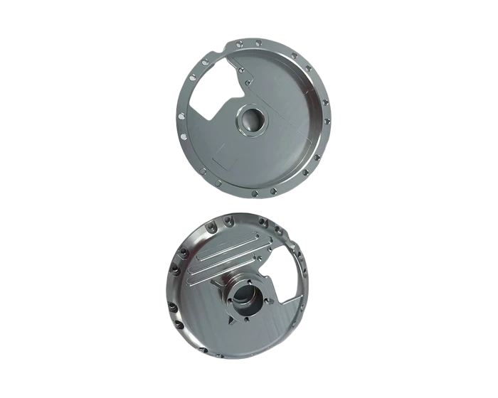
Rear Cover Flange in 6061-T6, Turned and Milled, Four Bearing Fits in One Part
6061-T6 rear cover flange, clear anodized: P.C.D. 58 bolt circle, central bearing fit cluster of H7, e7, g6 and P7, M2 thread pattern, position tolerances CMM verified. Quote in 24 hours.
General Industrial Components
A circular rear cover machined from 6061-T6 disc stock: multi-ring P.C.D. 58 hole pattern, a central stepped bore cluster in H7, g6 and P7 fits, an obround relief slot and an open notch, clear anodized and laser marked.
Or email drawings to kgl@kglmfc.com
Key Specifications
| Parameter | KGL Capability |
|---|---|
| Material | Aluminum alloy 6061-T6 (GB) |
| Bolt circle | P.C.D. 58 mm |
| Bearing fits | Ø53.50 H7 (effective precision depth over 3 mm), Ø62 e7, Ø17 g6, Ø10 P7 |
| Threads | 4x M2-6H equally spaced, plus 2x M2-6H through |
| Through holes | 8 positions of 2x Ø2.20 mm, equally spaced |
| Geometry tolerances | Coaxiality 0.008; position 0.012 to datum A; 0.004 form control |
| Default tolerances | GB/T1804-m linear, GB/T1184-K geometric, chamfers C0.2, radii R0.2, edges broken |
| Finish | Clear anodize, laser marked |
| Inspection | CMM on position and form, bore gauge on H7/g6/P7 fits, thread go no-go gauges, micrometer on key dimensions, film and appearance check |
| Tolerance | ±0.005 mm standard on metals, engineering plastics, and carbon fiber composite |
| Process | 5-axis CNC milling, 3+2 milling, CNC turning, EDM as required |
| Certifications | ISO 9001:2015, ISO 13485:2016, AS9100D |
| Capacity | 100+ CNC machines including 11 five-axis centers |
| MOQ | No MOQ; 1-piece prototypes supported |
| Quote | Within 24 hours for complete 2D/3D files |
About This Part
This rear cover shows how much capability hides in a familiar part shape. It is a circular flange-style cover for motors and gearboxes, machined from 6061-T6 disc stock, and almost everything on it is a mating interface: a bolt circle, a set of bearing fits around the center, a fine thread pattern, and a keyed orientation slot. The route is ordered so every later feature inherits one clean reference from the first operation.
Turning comes first. The blank is chucked as a disc, and the end faces and outside diameter are cut in one clamping, which establishes the axis every concentric feature will be measured from. Milling follows: the P.C.D. 58 hole rings, the obround lightening and routing slot, and the open notch that keys the cover to its housing are all cut with the turned rim as reference, so hole patterns and orientation features stay true to the bore axis rather than to the chuck jaws.
The center is where this part earns its tolerance. Four fits cluster around the axis: Ø53.50 H7 as the main precision bore with an effective precision depth over 3 mm, Ø62 e7 as the outer spigot, Ø17 g6 and Ø10 P7 as pilot and dowel locations. Fine boring all of them without re-clamping keeps the cluster concentric by construction. Coaxiality is held at 0.008, hole position at 0.012 to datum A, and a further form control at 0.004, all read on the CMM rather than inferred.
The small features are treated with the respect small features need. Four M2-6H holes are tapped on an even circle and two more run straight through, tapped by hand after chamfering so a 2 mm tap does not snap in a nearly finished part. Eight positions of paired Ø2.20 mm through holes are drilled on the same pattern. Edges are broken all around, with default chamfers at C0.2 and radii at R0.2, and general tolerances default to GB/T1804-m with geometric defaults at GB/T1184-K.
Finishing is clear anodize, which keeps the natural aluminum color while hardening the surface, followed by laser marking. Anodize grows a thin layer on every face including the bores, so film thickness is part of the fit conversation; masking the fits is available where the assembly needs bare metal. Inspection closes the route: CMM on position and form, bore gauge on the H7, g6 and P7 fits, thread go no-go gauges, micrometer checks on key dimensions, and a film and appearance check before packing.
This part family supports the Industrial Parts industry. Read how KGL machines parts for that sector, then send your drawing for a quote.
Why Machine It at KGL
Five-Axis Fleet
100+ CNC machines including 11 five-axis centers run complex geometry in single setups, so tolerances do not stack up across refixturing.
Verified Accuracy
±0.005 mm standard on metals, plastics, and carbon fiber composite, verified on Hexagon and Zeiss CMMs (0.0015 mm accuracy).
Fast Prototypes
Engineering feedback with every quotation; prototype parts typically machined in 15 to 25 days.
One Supplier, End to End
Material sourcing, machining, heat treatment coordination, finishing, CMM inspection and export packaging under one roof.
Part-Specific Advantages
- Four bearing related fits in one clamping: Ø53.50 H7, Ø62 e7, Ø17 g6, Ø10 P7
- Bore cluster fine bored without re-clamping, coaxiality 0.008 held by construction
- P.C.D. 58 hole rings, obround slot and open notch milled off the turned rim datum
- 4x M2-6H tapped on an even circle plus 2x M2-6H through, hand tapped after chamfering
- Position 0.012 to datum A and a 0.004 form control, both CMM verified
- Clear anodize with optional masking on fits, laser marking, edges broken at C0.2 and R0.2
Typical Applications
- Rear covers for motors and gearboxes
- Servo motor flange end covers
- Housing end caps for automation equipment
Commercial Terms
| Commercial | Detail |
|---|---|
| MOQ | No MOQ; 1-piece prototype supported |
| Quote | Within 24 hours for complete 2D/3D files |
| Terms | EXW / FOB Shenzhen |
| Certifications | ISO 9001:2015 |
| Packaging | Individual bubble wrap, export carton or wooden case |
| Lead Time | Prototypes 7 to 15 days; production scheduled by volume |
Common Questions
Why four different ISO fits on one cover?
Each bore pilots a different mating part: a bearing, a spigot register, a pilot pin, a dowel. Because all four are fine bored in the same clamping, their mutual alignment comes from the machine setup rather than from accumulated fixture error, which is what keeps the coaxiality at 0.008.
How do you tap M2 threads without breaking taps?
Small taps break when they cut dirty or start crooked. Every hole is chamfered first and the M2 holes are tapped by hand at the bench, so the tap feels the cut instead of forcing it. A broken tap in a nearly finished anodized-bound part costs the whole cover.
Does clear anodize affect the fit dimensions?
It can. The film adds a few microns per surface, which matters on H7 and g6 seats. Film thickness is part of the process plan, and where the assembly calls for bare metal in the bores we can mask the fits before coating, so tell us how the cover mates before we quote.
What tolerances can you hold on parts like this?
The drawing's own callouts govern, and the CMM verifies them. For new parts, send the tolerance band together with the service temperature and we will confirm what each feature can hold before quoting.
More General Industrial Components Parts
Other parts KGL machines in this industry. Every card links to its own detail page.
General Industrial Components
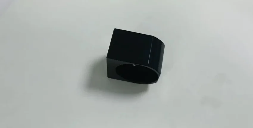
CNC Machining Chocolate Equipment Anodized Aluminum Slide Cover
View product →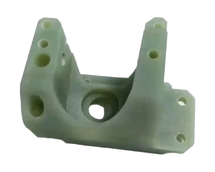
General Industrial Components
CNC Milling Industrial Equipment Filter Nozzle Mounting Base
View product →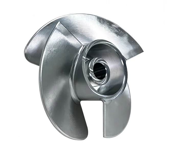
General Industrial Components
For Water SystemsCustom Milling Machining Impeller
View product →Ready to Machine This Part?
Send your 2D/3D drawings and get a quote within 24 hours. No MOQ for prototypes and small lots.
Request a Quote