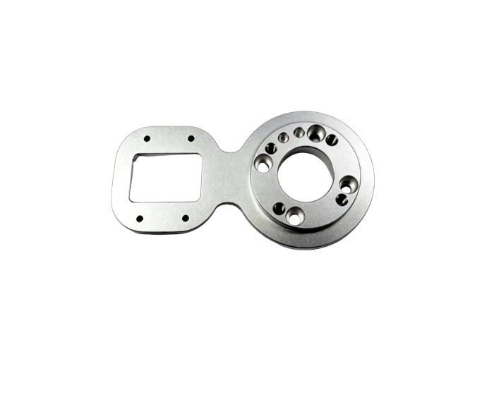
Figure 8 Servo Transition Flange Plate in 6061/7075 Aluminum, CNC Machined
Figure 8 transition flange plate in 6061-T6 or 7075-T6 aluminum: center distance held to plus or minus 0.02 mm, bearing bore coaxiality 0.015 mm, silver anodized. CMM checked 100 percent. Quote in 24 hours.
General Industrial Components
One piece flange plate that joins a rotary bearing or servo motor mount to a rectangular sensor or display module. The two centers are machined in one setup so the 0.02 mm center distance survives assembly.
Or email drawings to kgl@kglmfc.com
Key Specifications
| Parameter | KGL Capability |
|---|---|
| Material | Aluminum 6061-T6 or 7075-T6 |
| Process | 4 axis CNC milling both faces, bored bearing seat, high speed drilling and tapping, micro deburring |
| Center distance | +/-0.02 mm |
| Bearing bore coaxiality | 0.015 mm max |
| Thread position | 0.03 mm (M2.5 / M3 / M4) |
| Flatness and parallelism | 0.02 mm |
| Finish | Bead blast, matte silver anodized |
| Inspection | CMM 100 percent on center distance and position, air gauge on bore, thread go no go gauges, roughness meter |
| Tolerance | ±0.005 mm standard on metals, engineering plastics, and carbon fiber composite |
| Certifications | ISO 9001:2015, ISO 13485:2016, AS9100D |
| Capacity | 100+ CNC machines including 11 five-axis centers |
| MOQ | No MOQ; 1-piece prototypes supported |
| Quote | Within 24 hours for complete 2D/3D files |
About This Part
This plate carries two different mounting worlds on one body: a circular end that accepts a servo motor flange or bearing seat, and a rectangular framed end that hosts a vision sensor, display, or cable module. The two centers are positioned at a controlled distance of plus or minus 0.02 mm, and both are cut in a single clamping on a four axis machining center, so second op error never enters the equation.
The circular end carries a precision turned through bore for the motor or bearing fit, surrounded by a ring of counterbores, helicoil ready threaded holes, and mounting holes arranged on the bolt circle. The rectangular end is milled with a square through window for cable or optical access, with four symmetric counterbored fixing holes around it. M2.5, M3, and M4 threads across both faces hold position within 0.03 mm.
Machining runs from plate blank through both face milling, bore and window work, high speed drilling and tapping, then micro deburring before bead blast and silver anodize. The bearing bore coaxiality is held at 0.015 mm and face parallelism at 0.02 mm. Every plate is measured on the CMM for center distance and hole position before shipment, because these two numbers are what the assembler actually feels.
This part family supports the Industrial Parts industry. Read how KGL machines parts for that sector, then send your drawing for a quote.
Why Machine It at KGL
Five-Axis Fleet
100+ CNC machines including 11 five-axis centers run complex geometry in single setups, so tolerances do not stack up across refixturing.
Verified Accuracy
±0.005 mm standard on metals, plastics, and carbon fiber composite, verified on Hexagon and Zeiss CMMs (0.0015 mm accuracy).
Fast Prototypes
Engineering feedback with every quotation; prototype parts typically machined in 15 to 25 days.
One Supplier, End to End
Material sourcing, machining, heat treatment coordination, finishing, CMM inspection and export packaging under one roof.
Part-Specific Advantages
- Bearing bore coaxiality 0.015 mm, CMM verified on every part
- Center distance between the two cores held at plus or minus 0.02 mm
- M2.5, M3, and M4 threaded holes at 0.03 mm position tolerance
- Bead blast plus silver anodize for corrosion resistance and even appearance
- Face parallelism 0.02 mm on both reference sides
Typical Applications
- Servo motor flange mounting plates for gearboxes and encoders
- Vision or display module transition plates on automation cells
- High accuracy cross component positioning plates
Commercial Terms
| Commercial | Detail |
|---|---|
| MOQ | No MOQ; 1-piece prototype supported |
| Quote | Within 24 hours for complete 2D/3D files |
| Terms | EXW / FOB Shenzhen |
| Certifications | ISO 9001:2015 |
| Packaging | Individual bubble wrap, export carton or wooden case |
| Lead Time | Prototypes 7 to 15 days; production scheduled by volume |
Common Questions
Why machine both cores in one setup?
The 0.02 mm center distance is a stack of two positions. A second op flip introduces fixture error that eats most of that band, so the controlled features are cut before the part leaves the first clamp.
Will the anodize change my hole sizes?
Anodize builds a few microns per surface. Threads and the bearing bore are either masked, or final tapped and reamed after anodize, so mating hardware still fits.
More General Industrial Components Parts
Other parts KGL machines in this industry. Every card links to its own detail page.
General Industrial Components
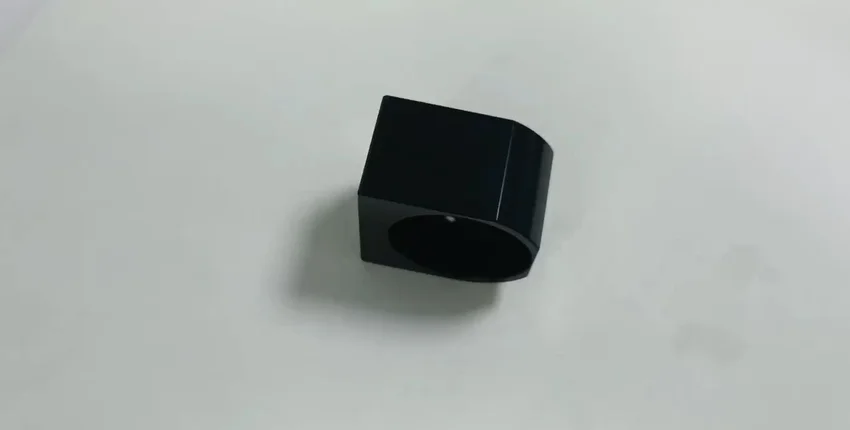
CNC Machining Chocolate Equipment Anodized Aluminum Slide Cover
View product →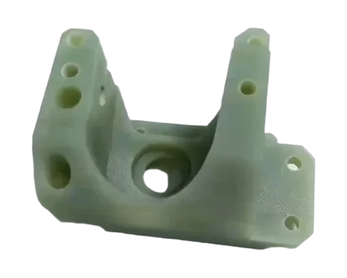
General Industrial Components
CNC Milling Industrial Equipment Filter Nozzle Mounting Base
View product →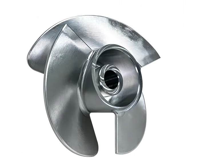
General Industrial Components
For Water SystemsCustom Milling Machining Impeller
View product →Ready to Machine This Part?
Send your 2D/3D drawings and get a quote within 24 hours. No MOQ for prototypes and small lots.
Request a Quote