CTS Slider Motor Mount in SUS316, 5-Axis Milled in One Setup, 100 Percent CMM Verified
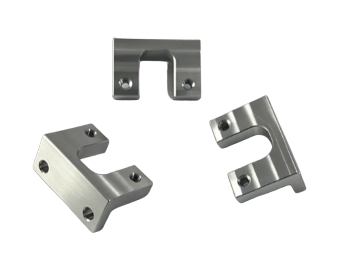
CTS SUS316 stainless steel slider motor mount, 28 x 20 x 13 mm, 11 mm wide U groove with R4.0 arc, 2x M3 threads and 2x 3.5 mm countersunk holes at plus or minus 0.05 mm, perpendicularity 0.01 to datum A, microscope deburred and 100 percent CMM inspected. Quote in 24 hours.
Medical Devices
The CTS slider motor mount is a small gate-shaped stainless bracket for a medical slider drive: thin 3.5 mm sidewalls around an 11 mm motor clearance groove, cross-drilled M3 locking threads, passivated bright finish, every part CMM and thread gauge verified.
Or email drawings to kgl@kglmfc.com
Key Specifications
| Parameter | KGL Capability |
|---|---|
| Material | SUS316 stainless steel |
| Overall size | Approx. 28 x 20 x 13 mm |
| Motor groove | U slot 11.0 mm wide, R4.0 full-radius arc |
| Threads | 2x M3 through, locking chamfer at entry |
| Fixing holes | 2x 3.5 mm countersunk, position +/-0.05 mm |
| Geometry tolerance | Perpendicularity and position 0.01 to datum A |
| Sidewall thickness | Approx. 3.5 mm |
| Chamfers | C0.1 default where not specified |
| Finish | Micro-brushed bright surface, passivated with electropolish step |
| Cleanliness | Burr-free, no scratches, dents or hard spots |
| Process | Bar stock cut, 5-axis CNC milling in one setup, drilling and tapping, microscope deburring, ultrasonic cleaning, passivation and electropolish |
| Inspection | M3 thread plug gauges on every part, CMM on groove radius, perpendicularity and hole positions, microscope surface check |
| Tolerance | ±0.005 mm standard on metals, engineering plastics, and carbon fiber composite |
| Certifications | ISO 9001:2015, ISO 13485:2016, AS9100D |
| Capacity | 100+ CNC machines including 11 five-axis centers |
| MOQ | No MOQ; 1-piece prototypes supported |
| Quote | Within 24 hours for complete 2D/3D files |
About This Part
This mount carries a small drive motor inside a medical slider mechanism, and its size is the first thing to understand: roughly 28 x 20 x 13 mm overall, with a gate-shaped section that leaves an 11 mm wide U groove across the top. The groove floor is a full-radius R4.0 arc that cradles the motor body, and the U sidewalls that support it are about 3.5 mm thick. A bracket this small with walls this thin leaves no spare material for machining mistakes.
The material adds its own difficulty. SUS316 is gummy and work hardens quickly, so a cutter that dwells skims the surface and hardens it instead of cutting, and the next pass meets a skin that pushes the tool sideways. On thin walls the result is not just a rough surface but a measurable lean: the sidewall bows inward under cutting pressure. The route counters this with small diameter coated tools, light layered finishing passes, and fresh edges, so the 11 mm groove width and the wall thickness both survive to the last pass instead of drifting as the cut progresses.
The hole pattern is where the part earns its tolerance. Two M3 threads run through the base with a locking chamfer at entry, and two 3.5 mm countersunk fixing holes sit on the flanges, arranged so the thread axis and the countersink axes cross at right angles. All of them are positioned to plus or minus 0.05 mm, and the mounting face carries a perpendicularity and position requirement of 0.01 to datum A. Tapping M3 in work-hardened stainless is its own risk: each hole is chamfered first and tapped with fresh taps so a 3 mm tap does not snap inside a nearly finished bracket.
Finishing is medical-grade housekeeping. Every part is deburred under a microscope, because a burr that would be invisible on a large part can shed into a mechanism this size. The parts then go through ultrasonic cleaning in purified water followed by passivation with an electropolish step, which leaves the bright, micro-brushed surface and removes the free iron that would otherwise start corrosion in service. The surface must come out clean and bright, with no burrs, scratches, dents or hard spots, and chamfers default to C0.1 where not otherwise specified.
Nothing on this part is sample inspected; everything is checked. M3 threads are gauged with go and no-go thread plug gauges on every part. The R4.0 groove radius, the perpendicularity and position to datum A, and the countersink positions are measured on the CMM, part by part. A final microscope pass confirms the polished surfaces are free of burrs and handling marks before the parts are packed.
This part family supports the Medical Device Parts industry. Read how KGL machines parts for that sector, then send your drawing for a quote.
Why Machine It at KGL
Five-Axis Fleet
100+ CNC machines including 11 five-axis centers run complex geometry in single setups, so tolerances do not stack up across refixturing.
Verified Accuracy
±0.005 mm standard on metals, plastics, and carbon fiber composite, verified on Hexagon and Zeiss CMMs (0.0015 mm accuracy).
Fast Prototypes
Engineering feedback with every quotation; prototype parts typically machined in 15 to 25 days.
One Supplier, End to End
Material sourcing, machining, heat treatment coordination, finishing, CMM inspection and export packaging under one roof.
Part-Specific Advantages
- 11 mm wide U groove with full R4.0 arc machined for motor cradling
- Approx. 3.5 mm thin sidewalls held straight with layered light finishing in SUS316
- 2x M3 through threads with locking chamfer, cross arranged with 2x 3.5 mm countersunk holes
- Hole position plus or minus 0.05 mm, perpendicularity and position 0.01 to datum A
- Microscope deburring, ultrasonic cleaning, passivation with electropolish, bright finish
- 100 percent inspection: thread plug gauges on all M3, CMM on groove, geometry and positions
Typical Applications
- Motor mounts for medical slider and actuator mechanisms
- Drive assemblies in compact diagnostic and analytical instruments
- Small stainless brackets where cross-arranged threads and precision geometry share one part
Commercial Terms
| Commercial | Detail |
|---|---|
| MOQ | No MOQ; 1-piece prototype supported |
| Quote | Within 24 hours for complete 2D/3D files |
| Terms | EXW / FOB Shenzhen |
| Certifications | ISO 9001:2015 |
| Packaging | Individual bubble wrap, export carton or wooden case |
| Lead Time | Prototypes 7 to 15 days; production scheduled by volume |
Common Questions
Why 5-axis milling for a bracket this small?
Because the features point in different directions. The U groove, the countersunk holes on the flanges and the cross-arranged M3 threads each face a different way, and one setup on a five-axis center machines them all without re-clamping. Every re-clamp on a 28 mm part is a fresh chance to lose the 0.01 mm geometry the drawing asks for.
How do you keep 3.5 mm walls straight in stainless?
Light cuts, layered finishing and sharp coated tools. SUS316 pushes back hard, and a heavy pass on a thin wall bows it inward permanently. Splitting the stock removal into light layers with fresh edges keeps the cutting pressure low enough that the walls come out flat and the 11 mm groove width stays true.
Is passivation enough for a medical environment?
For this bracket, the sheet calls for passivation with an electropolish step after ultrasonic cleaning, which removes free iron and leaves the bright corrosion-resistant surface 316 is chosen for. If your assembly needs a specific validation, tell us the standard it must meet and we will confirm the finishing route against it before quoting.
What tolerances can you hold on parts like this?
The drawing's own callouts govern, and the CMM verifies them on every part. For new parts, send the tolerance band together with the mating requirements and we will confirm what each feature can hold before quoting.
More Medical Devices Parts
Other parts KGL machines in this industry. Every card links to its own detail page.
Medical Devices
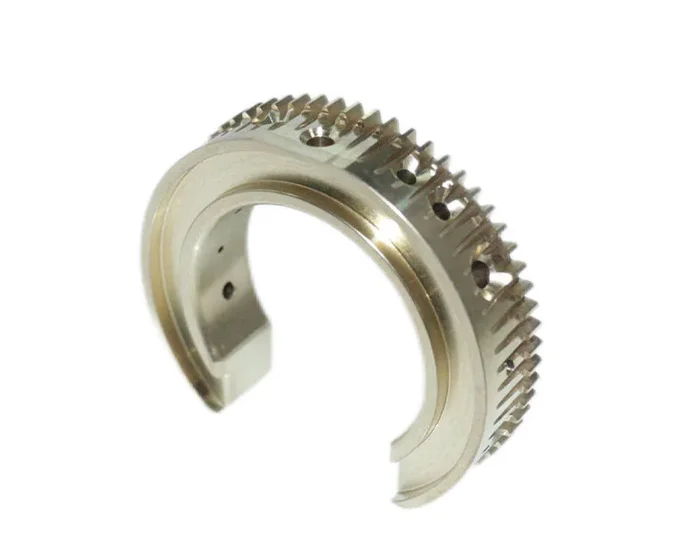
CNC Machining Medical Equipment Bracket and Automotive Rocker Arm Parts
View product →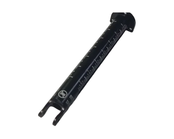
Medical Devices
CNC Machining Medical Orthopedic Aluminum External Fixator
View product →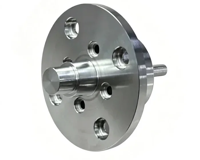
Medical Devices
CNC Milling Machining Rotary Motor Lock Aluminum Parts for Medical Equipment
View product →Ready to Machine This Part?
Send your 2D/3D drawings and get a quote within 24 hours. No MOQ for prototypes and small lots.
Request a Quote