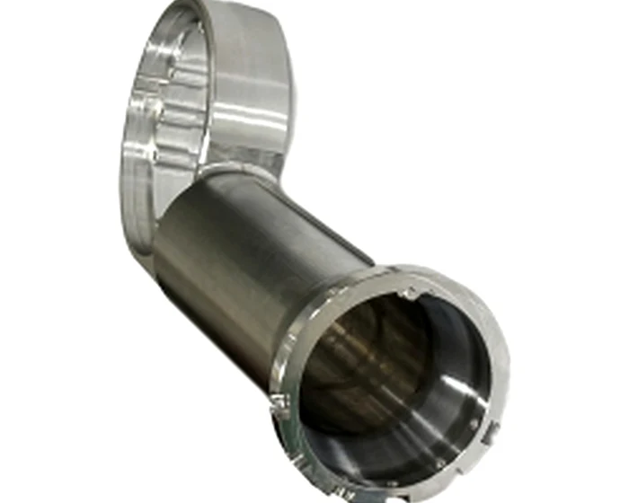
L-Shaped CNC Right Arm Rod, Internal Spline to Bolted Flange, Hollow Body
L-shaped right arm rod machined from 7075-T6 with an internal spline ring on one end and a bolted flange on the other, spline and flange completed in one setup so the two ends run concentric, spline gauged and every batch shipped with a CMM report. Quote within 24 hours.
Robotics & Humanoid Robots
A hollow L-shaped arm linkage for moving axes: the internal spline transmits torque from the drive side while the bolted flange carries the end effector, machined in a single setup so the rod rotates true without vibration.
Or email drawings to kgl@kglmfc.com
Key Specifications
| Parameter | KGL Capability |
|---|---|
| Product | L-shaped right arm rod (arm linkage) |
| Material | Aluminum 7075-T6 standard; stainless steel on request |
| Drive interface | Internal spline ring, machined to your spline drawing |
| Mounting interface | Bolted flange, hole pattern per drawing |
| Body | Hollow cylindrical tube, L geometry |
| Surface finish | Polished; Ra 0.8 or better on critical mating surfaces |
| Tolerance | Per drawing; critical features CMM inspected |
| Process | Five axis milling with spline cutting and polishing, single setup for both interfaces |
| Inspection | Go and no-go gauge on spline, CMM report with every batch |
| Photographs | Show the part as machined and polished, before any coating |
| Customization | Non-standard part, machined per your 2D drawing or 3D model |
| Certifications | ISO 9001:2015, ISO 13485:2016, AS9100D |
| Capacity | 100+ CNC machines including 11 five-axis centers |
| MOQ | No MOQ; 1-piece prototypes supported |
| Quote | Within 24 hours for complete 2D/3D files |
About This Part
This arm rod is the link between two rotating joints in automated equipment. One end carries an internal spline ring that mates with a motor or gearbox shaft; the opposite end is a bolted flange that secures the wrist or end effector. Between them runs a hollow cylindrical body bent into an L, and that hollow section is the design decision: it removes mass from a moving axis without giving up torsional stiffness, which shows up directly in acceleration and energy use.
The load path is mixed. The spline transmits torque while allowing radial alignment at assembly, the flange carries bending and the bolted connection, and the body sees both. That is why the two end interfaces are machined in a single setup on a five axis center: the spline bore and the flange bolt pattern come off the machine with their mutual position set by the machine axes rather than by a second clamping, so concentricity between the ends does not accumulate setup error. The finished rod rotates true, which is what a moving axis needs and what vibration complaints are usually about.
The internal spline is cut with dedicated tooling and verified with go and no-go gauges rather than judged by eye, and the flange hole positions are checked on the CMM together with spline dimensions and overall length. Body surfaces are polished; critical mating surfaces are held to Ra 0.8 or better because a polished interface on spline and bearing seats wears more slowly and runs quieter than a machined finish left as cut.
Material follows load and environment. Aluminum 7075-T6 carries the strength to weight ratio most automation arms want; stainless steel is available where corrosion or washdown calls for it. Bar stock arrives against mill certificates, and a second qualified source is held for common bar diameters so a material shortage does not stop a running batch. Every shipment leaves with a packing list, material certificate and CMM inspection report.
This part family supports the Robotics Parts industry. Read how KGL machines parts for that sector, then send your drawing for a quote.
Why Machine It at KGL
Five-Axis Fleet
100+ CNC machines including 11 five-axis centers run complex geometry in single setups, so tolerances do not stack up across refixturing.
Verified Accuracy
±0.005 mm standard on metals, plastics, and carbon fiber composite, verified on Hexagon and Zeiss CMMs (0.0015 mm accuracy).
Fast Prototypes
Engineering feedback with every quotation; prototype parts typically machined in 15 to 25 days.
One Supplier, End to End
Material sourcing, machining, heat treatment coordination, finishing, CMM inspection and export packaging under one roof.
Part-Specific Advantages
- L-shaped linkage transmits torque through an internal spline and mounts through a bolted flange
- Spline bore and flange pattern machined in one setup, so the two ends stay concentric without a second clamping
- Hollow cylindrical body cuts moving mass while holding torsional rigidity for faster axis response
- Internal spline cut with dedicated tooling and verified with go and no-go gauges
- Critical mating surfaces polished to Ra 0.8 or better for wear life and quiet running
- CMM report covering spline size, flange hole positions, concentricity and length with every batch
Typical Applications
- Robotic arm and wrist linkages between joint drives and end effectors
- Motion transfer links in automation equipment and gantry auxiliaries
- Replacement arm rods for system integrators and service fleets
Commercial Terms
| Commercial | Detail |
|---|---|
| MOQ | No MOQ; 1-piece prototype supported |
| Quote | Within 24 hours for complete 2D/3D files |
| Terms | EXW / FOB Shenzhen |
| Certifications | ISO 9001:2015 |
| Packaging | Foam tray, spline and polished faces capped, export carton or wooden case |
| Lead Time | Prototypes 7 to 15 days; production scheduled by volume |
Common Questions
How do you keep the spline and flange concentric?
Both end interfaces are machined in a single setup, so their mutual position comes from the machine axes instead of a second clamping. Concentricity is then verified on the CMM and reported with the batch.
Can you machine a different spline size or flange pattern?
Yes. Send your 2D drawing (PDF, DWG, DXF) or 3D model (STEP, IGES) with the spline specification and flange hole pattern, and the rod is machined to match your joint interface exactly.
Which material should the arm rod be?
Aluminum 7075-T6 is the default for strength to weight on moving axes. Stainless steel suits corrosion or washdown environments. Send the load and environment with the drawing and we recommend the grade.
What is the MOQ, quote speed and lead time?
No MOQ, prototypes start from 1 piece. A complete 2D/3D file set gets a quotation within 24 hours. Prototypes run 7 to 15 days and production batches are scheduled by volume.
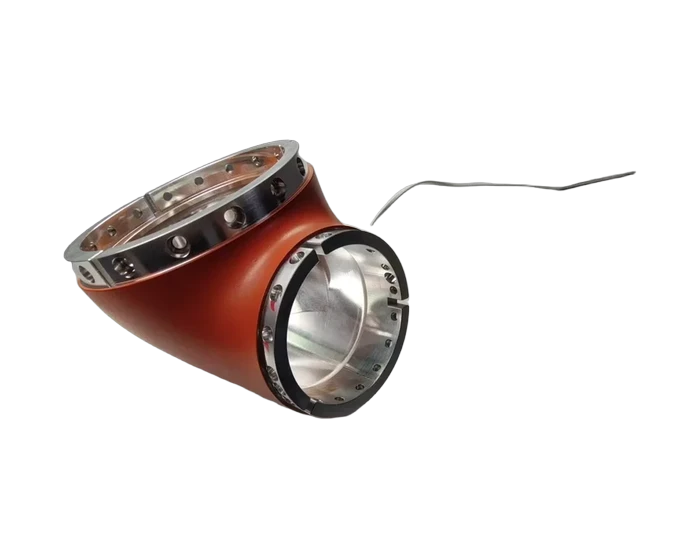
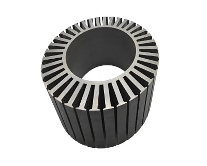
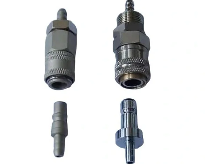
More Robotics & Humanoid Robots Parts
Other parts KGL machines in this industry. Every card links to its own detail page.
Ready to Machine This Part?
Send your 2D/3D drawings and get a quote within 24 hours. No MOQ for prototypes and small lots.
Request a Quote