Robot Arm Frame in AL6061/7075-T6, One-Piece Milled with Lightening Cavities, Coaxiality 0.015 mm
Robotic multi-axis arm frame, 220 to 300 mm long, 5-axis milled in one piece from aluminum billet with matrix lightening cavities, flange bores at H7 +0.021/0 mm, bearing seat coaxiality within 0.015 mm, flatness 0.02 mm, bead blasted clear anodized. Quote in 24 hours.
Robotics & Humanoid Robots
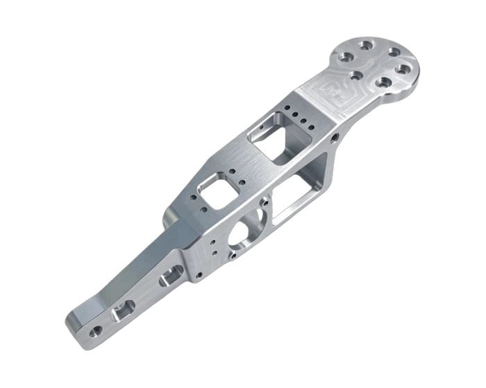
A one-piece multi-axis robot arm frame milled from thick aluminum plate: matrix lightening cavities cut the moving inertia, while flange bores at H7 and a bearing seat coaxial to 0.015 mm keep the joint stack aligned.
Or email drawings to kgl@kglmfc.com
Key Specifications
| Parameter | KGL Capability |
|---|---|
| Material | Aluminum 6061-T6 / 7075-T6 |
| Length | Approx. 220 to 300 mm |
| Width | Approx. 60 to 100 mm |
| Flange holes | H7, +0.021/0 mm, PCD spaced with dowel holes |
| Bearing seat | H7 / H8 fits, coaxiality 0.015 mm max |
| Flatness | 0.02 mm max on key faces |
| Perpendicularity | 0.03 mm to datum faces |
| Finish | Fine bead blast with clear anodize |
| Process | Thick plate stock, 5-axis rough milling of profile and cavities with de-stress, 5-axis finish milling of contour and faces, precision bore, drill, ream and tap, microscope deburring, ultrasonic cleaning, bead blast and anodize |
| Inspection | 100 percent CMM on bearing bore coaxiality, flange PCD position, face flatness and perpendicularity; thread plug gauges on all tapped holes; caliper and depth gauge on outside dimensions |
| Tolerance | ±0.005 mm standard on metals, engineering plastics, and carbon fiber composite |
| Certifications | ISO 9001:2015, ISO 13485:2016, AS9100D |
| Capacity | 100+ CNC machines including 11 five-axis centers |
| MOQ | No MOQ; 1-piece prototypes supported |
| Quote | Within 24 hours for complete 2D/3D files |
About This Part
An arm is the part a robot accelerates thousands of times a day, so weight that survives in a static bracket is inertia here. This frame is milled in one piece from 220 to 300 mm aluminum plate, with its interior excavated into a matrix of lightening cavities and reinforcing ribs. The walls that remain carry the bending and torsion loads; the volume that is gone no longer fights the motors. One-piece milling keeps all of the mounting faces and bores in one rigid body instead of a weldment that can move over time.
The interfaces are the accuracy. One end carries a circular flange with a PCD pattern of tapped and dowel holes at H7, +0.021/0 mm; the mid-body houses a bearing seat and motor spigot bored to H7/H8 fits with coaxiality within 0.015 mm; and the mounting faces hold flatness within 0.02 mm with 0.03 mm perpendicularity to the datum faces. Because the part is machined across five faces, the five-axis center carries it through multi face fixturing in one or very few setups, so the holes and bores reference each other instead of accumulating setup error.
Cavity milling thins the walls, and thin walls move under cutting heat and residual stress. The route is staged: rough the profile and cavities with finish stock left on, let the part relax, then run the five-axis finishing of the external contour, flange and mounting faces, then precision bore the bearing seat and drill, ream and tap the hole arrays. Every intersecting hole is deburred under magnification, because a burr inside a joint assembly is a failure waiting for assembly day.
The frame is ultrasonically cleaned, fine bead blasted and clear anodized, then verified with a full CMM pass: bearing bore coaxiality, flange PCD position, and perpendicularity and flatness on every datum face, with thread plug gauges in every tapped hole.
This part family supports the Robotics Parts industry. Read how KGL machines parts for that sector, then send your drawing for a quote.
Why Machine It at KGL
Five-Axis Fleet
100+ CNC machines including 11 five-axis centers run complex geometry in single setups, so tolerances do not stack up across refixturing.
Verified Accuracy
±0.005 mm standard on metals, plastics, and carbon fiber composite, verified on Hexagon and Zeiss CMMs (0.0015 mm accuracy).
Fast Prototypes
Engineering feedback with every quotation; prototype parts typically machined in 15 to 25 days.
One Supplier, End to End
Material sourcing, machining, heat treatment coordination, finishing, CMM inspection and export packaging under one roof.
Part-Specific Advantages
- One-piece 5-axis milled arm frame, no weldments to move over time
- Matrix lightening cavities cut moving inertia while ribs carry the load
- Flange PCD holes at H7 +0.021/0 mm for dowel located mounting
- Bearing seat and motor spigot coaxial within 0.015 mm
- Flatness 0.02 mm on mounting faces, perpendicularity 0.03 mm to datums
- Microscope deburring of all intersecting holes, bead blasted clear anodize
Typical Applications
- Multi-axis robot arm and joint structural frames
- Lightweight link structures for humanoid and collaborative robots
- Billet milled aluminum frames where flange, bearing bore and faces must stay aligned
Commercial Terms
| Commercial | Detail |
|---|---|
| MOQ | No MOQ; 1-piece prototype supported |
| Quote | Within 24 hours for complete 2D/3D files |
| Terms | EXW / FOB Shenzhen |
| Certifications | ISO 9001:2015 |
| Packaging | Individual bubble wrap, export carton or wooden case |
| Lead Time | Prototypes 7 to 15 days; production scheduled by volume |
Common Questions
Why mill from one billet instead of fabricating?
Because the frame is the reference for everything bolted to it. A one-piece milled frame keeps the flange, bearing bore and mounting faces in one rigid body with one datum chain, and it cannot shift the way a welded assembly can under vibration.
Do the lightening cavities weaken it?
No, they are designed, not just removed. The remaining walls form a rib network sized for the bending and torsion loads of the joint, and the weight they remove is inertia the motors no longer pay for on every move.
How is the bearing bore kept coaxial across so many faces?
The bore is precision bored in the same setup chain as the datum faces on the five-axis center, and the CMM verifies coaxiality within 0.015 mm on every frame rather than sampling.
What tolerances can you hold on new arm frames?
The drawing's own callouts govern. Send the tolerance band together with the bearing and flange interfaces, and we will confirm feature by feature what can be held before quoting.
More Robotics & Humanoid Robots Parts
Other parts KGL machines in this industry. Every card links to its own detail page.
Ready to Machine This Part?
Send your 2D/3D drawings and get a quote within 24 hours. No MOQ for prototypes and small lots.
Request a Quote