Large Thin Panel Control Baseplate in 6061-T6, Double Side CNC Milled
300 mm class thin control baseplate in 6061-T6: flatness 0.05 mm over the full panel, bore pattern position 0.02 mm, conductive anodize or chromate finish. Vacuum fixtured, CMM checked. Quote in 24 hours.
Semiconductor & Optics
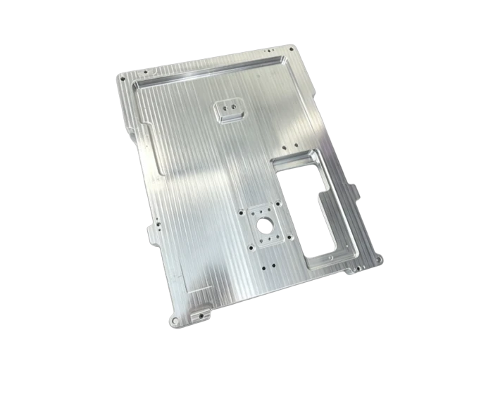
A 300 mm plus rectangular thin panel with pockets on both faces, a large L shaped cable and airflow window, and a central bearing seat with an eight hole bolt pattern. Built for semiconductor test equipment frames.
Or email drawings to kgl@kglmfc.com
Key Specifications
| Parameter | KGL Capability |
|---|---|
| Material | Aluminum 6061-T6 |
| Process | Gantry and vertical CNC milling, vacuum fixturing, staged symmetric roughing, both face finishing |
| Panel span | 300 mm and larger |
| Flatness | 0.05 mm max full panel |
| Bore pattern position | 0.02 mm |
| Pocket depth | +/-0.03 mm |
| Finish | Conductive anodize or chromate conversion, RoHS |
| Inspection | Gantry CMM 100 percent flatness and coordinates, depth micrometer, thread gauges |
| Tolerance | ±0.005 mm standard on metals, engineering plastics, and carbon fiber composite |
| Certifications | ISO 9001:2015, ISO 13485:2016, AS9100D |
| Capacity | 100+ CNC machines including 11 five-axis centers |
| MOQ | No MOQ; 1-piece prototypes supported |
| Quote | Within 24 hours for complete 2D/3D files |
About This Part
Test equipment frames want stiffness without mass, and this baseplate is the compromise done properly: a 300 mm plus span milled thin, both faces pocketed to remove weight, and the residual stress managed with staged symmetric roughing on vacuum fixturing so the panel stays flat at 0.05 mm or better.
The right lower region carries a large L shaped through window for cable routing and airflow. The center holds a circular bearing seat with a ring of eight tapped holes, and the rest of the panel carries dozens of M2.5, M3, and M4 threads plus dowel holes for mounting boards, sensors, and covers. Deep pocket depths hold plus or minus 0.03 mm.
After machining the plate is micro deburred, ultrasonically cleaned, and finished with conductive anodize or chromate conversion for grounding and corrosion protection. The CMM runs 100 percent flatness and coordinate checks with a gantry machine large enough for the full span.
This part family supports the Optical / Semiconductor Parts industry. Read how KGL machines parts for that sector, then send your drawing for a quote.
Why Machine It at KGL
Five-Axis Fleet
100+ CNC machines including 11 five-axis centers run complex geometry in single setups, so tolerances do not stack up across refixturing.
Verified Accuracy
±0.005 mm standard on metals, plastics, and carbon fiber composite, verified on Hexagon and Zeiss CMMs (0.0015 mm accuracy).
Fast Prototypes
Engineering feedback with every quotation; prototype parts typically machined in 15 to 25 days.
One Supplier, End to End
Material sourcing, machining, heat treatment coordination, finishing, CMM inspection and export packaging under one roof.
Part-Specific Advantages
- Full panel flatness 0.05 mm on a 300 mm plus thin span
- Center bore and 8 hole array position within 0.02 mm
- L shaped cable and airflow window, both faces pocketed for weight
- Dozens of M2.5 / M3 / M4 threads with complete burr free tapping
- Conductive anodize or chromate finish, RoHS compliant
Typical Applications
- Structural control baseplates for semiconductor test equipment
- Grounding baseplates for instrument frames needing EMI control
- Lightweight mounting panels for automation and inspection machines
Commercial Terms
| Commercial | Detail |
|---|---|
| MOQ | No MOQ; 1-piece prototype supported |
| Quote | Within 24 hours for complete 2D/3D files |
| Terms | EXW / FOB Shenzhen |
| Certifications | ISO 9001:2015 |
| Packaging | Individual bubble wrap, export carton or wooden case |
| Lead Time | Prototypes 7 to 15 days; production scheduled by volume |
Common Questions
How do you keep a thin 300 mm plate flat?
High material removal means released stress. We rough symmetrically on vacuum fixturing, let the panel relax between ops, then finish both faces against a verified reference before the final anodize.
Conductive anodize or chromate, which one?
Conductive anodize when the panel must carry ground to mounted boards. Chromate when maximum dimensional stability matters more, since conversion coatings add almost no thickness.
More Semiconductor & Optics Parts
Other parts KGL machines in this industry. Every card links to its own detail page.
Semiconductor & Optics
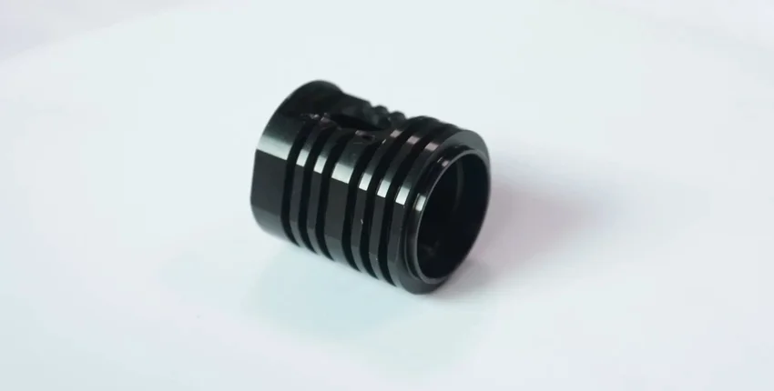
Custom CNC Precision Machining Semiconductors Packaging Inspection Equipment and Automation Parts
View product →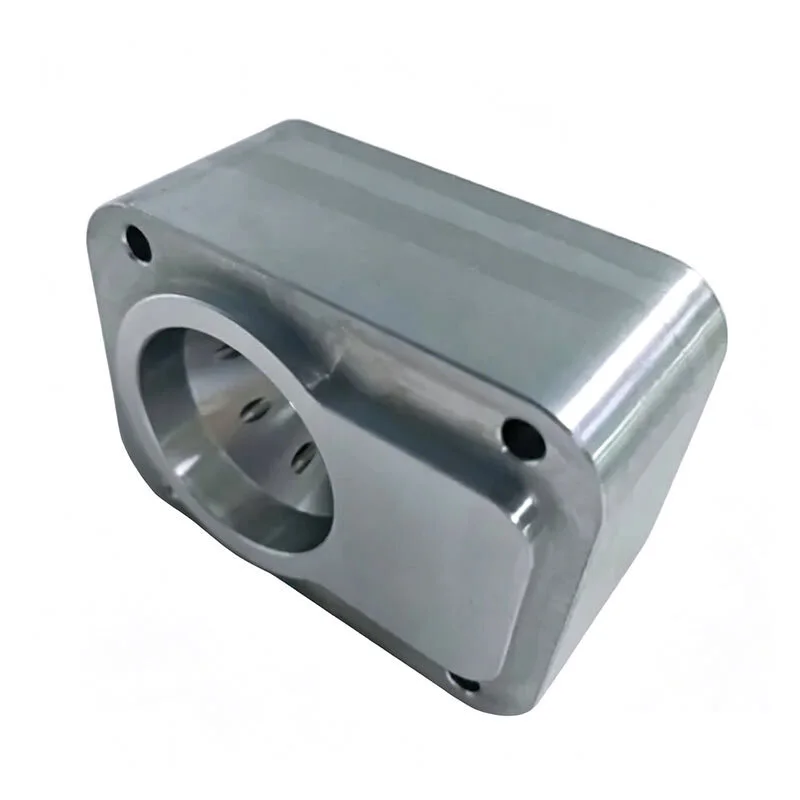
Semiconductor & Optics
Microscope Quad Lens Seals for Medical and Laboratory Use
View product →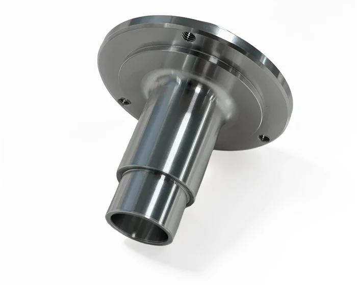
Semiconductor & Optics
OEM Custom CNC Precision Machining Semiconductors and Automation Part
View product →Ready to Machine This Part?
Send your 2D/3D drawings and get a quote within 24 hours. No MOQ for prototypes and small lots.
Request a Quote