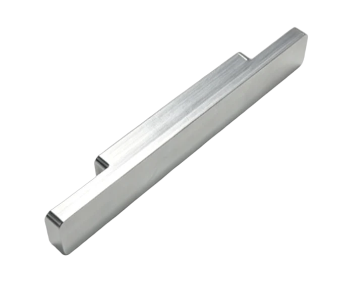
Linear Scale Positioning Fixture, 5-Axis Milled from 6061-T6, 124 mm Long
6061-T6 linear scale positioning fixture, 124 x 18 x 10 mm, 0.39 mm deep 90 degree V grooves held at 0/-0.03 mm, Ra 1.6 working faces, black anodized. Quote in 24 hours.
Semiconductor & Optics
A slender 6061-T6 fixture bar with a 74 mm stepped working section, 0.39 mm deep 90 degree V grooves, end radii of R3 and transverse grip ridges, made for nesting linear scales and optical elements.
Or email drawings to kgl@kglmfc.com
Key Specifications
| Parameter | KGL Capability |
|---|---|
| Material | Aluminum alloy 6061-T6 |
| Overall size | 124.00 x 18.00 x 10.00 mm |
| Working section | 74.00 mm stepped section between R3 end radii |
| V grooves | 0.39 mm deep, 0/-0.03 mm, 90 degree included angle |
| Slot widths | 4.10 mm and 5.00 mm |
| End radii | R3 transitions at both ends |
| Surface roughness | Ra 1.6 on critical working faces, Ra 3.2 general |
| Burr requirement | No burrs permitted inside the grooves |
| Finish | Black anodized, sealed |
| Photographs | Show the fixture as machined, before anodizing, so the milled detail stays visible |
| Process | Precision blank cut, 4/5-axis CNC milling, microscope deburring, black anodize |
| Inspection | 2D vision measuring machine with microscope optics on groove depth, angle and width; magnified groove interior check; caliper and height gauge on length and thickness |
| Tolerance | ±0.005 mm standard on metals, engineering plastics, and carbon fiber composite |
| Certifications | ISO 9001:2015, ISO 13485:2016, AS9100D |
| Capacity | 100+ CNC machines including 11 five-axis centers |
| MOQ | No MOQ; 1-piece prototypes supported |
| Quote | Within 24 hours for complete 2D/3D files |
About This Part
This fixture is a thin, long bar, 124 mm end to end on an 18 by 10 mm section, and that proportion is what makes it interesting to machine. A part this slender will bow the moment a cutter leans on it, so the route is built around keeping the bar relaxed: multi-pass clamping, light finishing cuts, and the part given every chance to settle before the last pass on each face.
The working geometry sits in the middle of the bar. Milling leaves a 74 mm stepped section between R3 transition radii at the ends, and into that section go the precision V grooves. Each groove is 0.39 mm deep with a 90 degree included angle, held to 0/-0.03 mm on depth, alongside 4.10 mm and 5.00 mm slot widths. These grooves are what seat the scale or optical element, so their depth and angle decide whether the mating part sits on the groove flank or rocks on its edge.
Micro grooves this shallow are cut with small finishing tools at light depth of cut, and the burr question is taken as seriously as the size. The technical requirement states no burrs inside the grooves, so every groove is deburred under magnification before the part moves on. Both ends carry transverse ridges for grip and location, machined in the same setup as the grooves so the pattern stays aligned along the bar.
Surface finish is specified two ways: Ra 3.2 as the general finish and Ra 1.6 on the critical working faces, which is where the mating element actually touches. After deburring the bar goes through black anodize with a sealing treatment. Film thickness matters here, because anodize grows on every face and the 0.39 mm groove depth and the 4.10 mm slot width have to stay in tolerance after coating, so the film is controlled rather than left to chance.
The photographs on this page show the fixture as machined, before anodizing, so the milled V grooves, the transition radii, the grip ridges and the tool finish can be read directly instead of being hidden under the coating. Customers who want to judge the machining state before surface treatment get it straight from these images.
Inspection runs on a 2D vision measuring machine with microscope optics, reading the 0.39 mm groove depth, the 90 degree angle, and the 4.10 mm slot width directly. Groove interiors are examined under magnification to confirm they are burr free, and overall length and the 10 mm thickness are checked with calipers and a height gauge.
This part family supports the Optical / Semiconductor Parts industry. Read how KGL machines parts for that sector, then send your drawing for a quote.
Why Machine It at KGL
Five-Axis Fleet
100+ CNC machines including 11 five-axis centers run complex geometry in single setups, so tolerances do not stack up across refixturing.
Verified Accuracy
±0.005 mm standard on metals, plastics, and carbon fiber composite, verified on Hexagon and Zeiss CMMs (0.0015 mm accuracy).
Fast Prototypes
Engineering feedback with every quotation; prototype parts typically machined in 15 to 25 days.
One Supplier, End to End
Material sourcing, machining, heat treatment coordination, finishing, CMM inspection and export packaging under one roof.
Part-Specific Advantages
- 0.39 mm deep, 90 degree V grooves held to 0/-0.03 mm on depth
- 124 mm slender bar milled with multi-pass clamping and stress relief to keep it straight
- 74 mm stepped working section between R3 transition radii
- Working faces finished to Ra 1.6, general surfaces Ra 3.2
- Grooves deburred under magnification, no burrs permitted inside
- Black anodize with film thickness controlled so groove depth and slot width stay in tolerance
Typical Applications
- Nesting and positioning of linear scales on measurement equipment
- Mounting fixtures for optical elements and grating assemblies
- Alignment bars for semiconductor and inspection apparatus
Commercial Terms
| Commercial | Detail |
|---|---|
| MOQ | No MOQ; 1-piece prototype supported |
| Quote | Within 24 hours for complete 2D/3D files |
| Terms | EXW / FOB Shenzhen |
| Certifications | ISO 9001:2015 |
| Packaging | Individual bubble wrap, export carton or wooden case |
| Lead Time | Prototypes 7 to 15 days; production scheduled by volume |
Common Questions
How do you keep a 124 mm slender bar from bowing?
The bar is clamped in multiple passes and the cuts are split between roughing and finishing. Roughing releases the stress in the stock and the part moves; finishing after it settles takes light cuts that leave the straightness in, instead of locking a bow into the last pass.
How do you measure a 0.39 mm deep V groove?
On a 2D vision measuring machine with microscope optics. Depth, the 90 degree included angle, and the 4.10 mm slot width are all read optically, which suits a feature too small and too sharp for a physical probe to touch without distorting the reading.
Does anodizing change the groove dimensions?
It can, because the film grows on every surface including the groove flanks. That is why film thickness is controlled rather than left open, so the 0.39 mm depth and the 4.10 mm width still sit inside their tolerance after sealing.
What tolerances can you hold on this fixture?
The drawing carries its own callouts for the grooves and slots, and we work to the drawing. For new parts, send the tolerance band together with the service temperature and we will confirm feature by feature what can be held.
More Semiconductor & Optics Parts
Other parts KGL machines in this industry. Every card links to its own detail page.
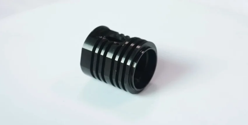
Semiconductor & Optics
Custom CNC Precision Machining Semiconductors Packaging Inspection Equipment and Automation Parts
View product →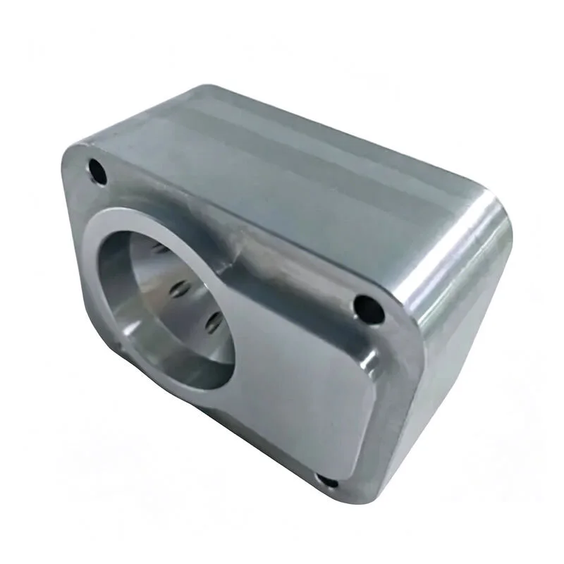
Semiconductor & Optics
Microscope Quad Lens Seals for Medical and Laboratory Use
View product →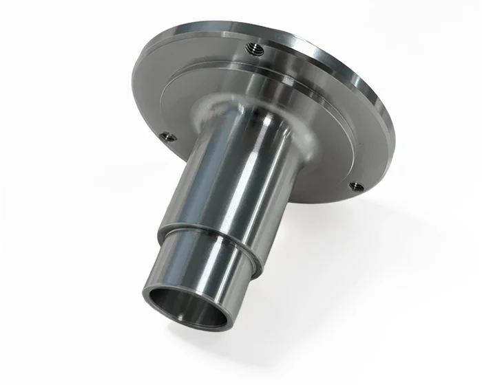
Semiconductor & Optics
OEM Custom CNC Precision Machining Semiconductors and Automation Part
View product →Ready to Machine This Part?
Send your 2D/3D drawings and get a quote within 24 hours. No MOQ for prototypes and small lots.
Request a Quote