CNC Machining for New Energy Vehicles: Key Components and Materials
CNC machined components for new energy vehicle and energy systems: battery housings, cooling plates, busbars, motor and reducer parts, plus the aluminum, copper, and steel choices behind them.
New energy changed what machine shops are asked to make. Battery systems, thermal management, fuel cell stacks, and charging hardware replaced a lot of traditional drivetrain volume with parts that are thinner, more thermally critical, and less forgiving of burrs than what they replaced. We machine components for these programs, and our new energy machining page lists the part families. This guide walks through the components, the materials behind them, and the machining realities that decide whether a quote comes back at a workable number.
1. What these parts demand from the process
Three requirements repeat across the category. First, sealing and thermal surfaces: cooling plates and housings live or die on flatness, because a warped thermal interface turns into a hot spot no software can fix. Second, electrical contact: busbar and connection faces need clean, burr free geometry, because a stray burr in a high voltage path is a failure waiting for vibration. Third, consistency: platform production runs need the last part in the batch to match the first article, shift after shift, which is a process control question more than a machine question.
2. The components, and what each one needs
Battery housings, module frames, and connection plates combine thin walls with sealing faces. The machining challenge is holding flatness on large faces while removing enough material to keep the weight target. Cooling plates and heat sinks add internal flow channels: the channel geometry must seal and the mounting faces must stay flat after brazing or welding neighbors do their thing. We cover our typical families on the new energy page.
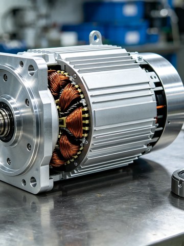
Motor and actuator housings, end covers, and reducer parts sit in the same machining family: large diameters, bearing seats, and sealing surfaces where concentricity and squareness decide noise and life. We quote these per drawing, and the same fixturing discipline carries over from our robotics housing work.
Charging hardware and power electronics housings bring the electrical contact requirements back: clean contact faces, controlled edge breaks, and surface finishes that do not shed particles into connectors.
3. Materials, and why they pair the way they do
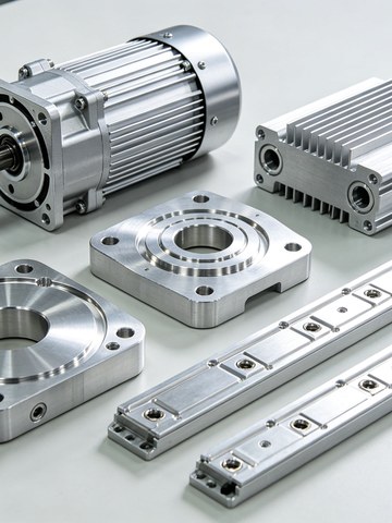
Aluminum carries most of the category. 6061, 6063, and 7075 form housings, cooling plates, and brackets because they combine low weight, good thermal conductivity, and clean machinability; our 7075 vs 6061 comparison covers the trade when strength joins the requirement.
Copper and its alloys carry the current. Busbars and connectors need burr free contact surfaces, and copper machines cleanly with sharp tooling and controlled speeds. Beryllium copper appears where spring contact force is part of the design.
Stainless steel takes the corrosion and safety critical roles: sensor housings, fasteners, and protective parts exposed to weather and road chemicals. Our stainless steel guide covers the grade choices.
| Component | Typical material | Key machining requirement |
|---|---|---|
| Motor housing / end cover | Aluminum 6061, 6063, 7075 | Concentricity, flatness, sealing surfaces |
| Battery busbar / connector | Copper C1100, beryllium copper | Burr free edges, precise contact surfaces |
| Cooling plate / heat sink | Aluminum 6063 | Flow channel accuracy, face flatness |
| Structural bracket / mount | Aluminum 6061, steel | Strength, low weight, consistent geometry |
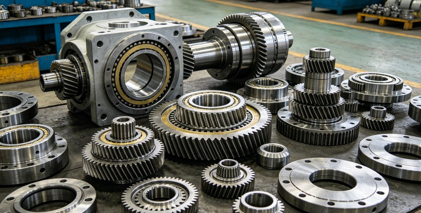
| Reducer / shaft / housing | Steel, aluminum | Bore tolerance, spline accuracy, surface finish |
4. Where these parts get difficult on the machine
Thin walls are the first fight. Lightweight housings flex away from the cutter and ring when the engagement is wrong, so the answers are process answers: balanced clamping, sharp tooling, and five axis strategies that reach features in fewer setups, which our five axis machining page describes. Second is thermal movement on large aluminum parts: cutting sequence and heat input decide whether the part holds tolerance on the CMM at room temperature and in service. Third is cleanliness: contact faces, sealing faces, and cooling surfaces get deburred, edge finished, and cleaned as part of the route, not as an afterthought before packing.
5. How a quote for these parts actually runs
Send the drawing with the sealing and contact faces called out, and the quote prices what the part needs: flatness verified on Hexagon and Zeiss CMMs, surface treatment planned with the machining, and batch consistency checked against the first article. Our standard tolerance on machined features is plus or minus 0.005 mm, with tighter bands on specific features where full CMM verification supports them. Prototyping starts at one piece with no MOQ, and production runs ride the same process chain.
6. FAQ
Can you hold flatness on large cooling plates?
Yes. Flatness on thermal and sealing faces is verified on the CMM, and the route sequences roughing, stress relief, and finishing so the plate is flat at room temperature, not just on the machine.
Do you machine copper busbars and connectors?
Yes. Sharp tooling and controlled speeds give clean, burr free contact surfaces, and edge breaks are controlled where connectors mate.
What about thin wall housings that distort?
Torque controlled clamping, backup supports, and five axis strategies that cut more features per setup. Distortion is a process design problem, and it is priced into the route from the start.
Do you support prototype to production on the same drawing?
Yes. One-piece sampling with no MOQ, then batch production under the same process chain and quality system, so the approved sample is the part you receive at volume.
If you are sourcing machined parts for a new energy program, send your STEP or IGES models and 2D drawings to kgl@kglmfc.com or request a quote on our RFQ page. We will review the sealing and contact faces, quote within 24 hours, and tell you which callouts are driving the cost.
Related Articles
More from the New Energy & EV series.
Have a project in mind?
Send drawings to kgl@kglmfc.com or request a quote. We respond within 24 hours.
Request a Quote