CNC Machining for Wind and Solar Equipment: Fits That Last Decades
Wind and solar machined parts must survive twenty years outdoors: bearing seat fits, thermal movement between steel and aluminum, and coating system life
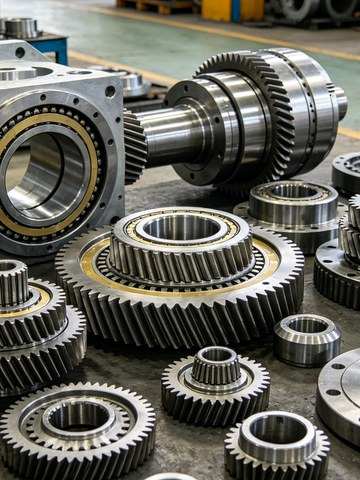
Energy hardware is sold on a twenty year promise and built in a supply chain that has eighteen months to deliver. That combination puts unusual pressure on machined parts, because they sit at the joints where a generator, a gearbox, a blade pitch system or a tracker drive connects to a structure that will move, flex and corrode for two decades. A tolerance missed by 20 micrometres becomes a warranty event at year seven, when the crane cost to reach the part exceeds the part price by an order of magnitude.
This guide covers what machined components actually do in wind and solar equipment: the drivetrain fits that decide noise and bearing life, the material and coating choices that survive weather and salt, the thermal arithmetic that governs joints between steel and aluminum, and the way large welded and cast structures are machined so that accuracy survives the trip to site.
At a glance
- Drivetrain housings are judged on coaxiality and squareness, not on individual diameters. Two perfect bores that are 0.05 mm out of line will preload a shaft.
- A 2 m steel member and an aluminum bracket in the same assembly move roughly 1.4 mm relative to each other over a 60 K swing. The joint has to be designed for that movement.
- Coating lifetime is decided by surface preparation and edge geometry as much as by the coating itself, and both are influenced by machining.
- Weldments must be stress relieved before finish machining. Machining first and welding later guarantees a rework loop.
1. Why Are Drivetrain Fits Measured in Microns While the Structure Is Measured in Tonnes?
A 3 MW drivetrain can weigh tens of tonnes and still depend on a few bearing seats held to 20 or 30 micrometres. The reason is load distribution. A spherical roller bearing that sits in a housing bore with the correct interference shares load across its full complement of rollers. The same bearing in a bore that is round but out of square by 0.02 mm runs with one edge loaded, and the resulting heat and vibration show up as a seal failure first, then as a bearing failure that is blamed on the bearing supplier.
In practice the controlling calls on a gearbox or main bearing housing are a bore diameter at H7, a shoulder squareness around 0.01 mm, and a coaxiality between the front and rear seats in the 0.02 to 0.05 mm range depending on the span. Coaxiality is the one that gets lost in translation, because it cannot be verified by measuring each bore separately. It requires a CMM evaluation against a common datum, or a mandrel and dial indicator check that spans both bores. We report it as a single value for the pair, because a report that lists two diameters and leaves the relationship to the reader is not a report. The same discipline runs through our inspection workflow.
The same logic applies to the interfaces around the drivetrain. A pitch bearing seat that is flat within 0.05 mm over its face keeps the bearing from rocking. A yaw gear mounting face that is out of parallel by 0.1 mm across a metre introduces a misalignment that the gear teeth convert into noise and wear. These are large features on large parts, and the only reliable way to hold them is to finish them in one setup with in process probing, so the machine corrects for the casting rather than assuming it.
2. What Does Twenty Years Outdoors Do to Material Choice?
Corrosion is a design decision, and the machined part has to cooperate with it. A tower internals bracket in plain carbon steel will be galvanized, and hot dip galvanizing adds 60 to 85 micrometres per surface, which is enough to close a clearance or block a tapped hole if the drawing did not account for it. That is why the process sequence matters: machine the threads after galvanizing, or mask them, or specify a zinc flake coating that goes on thin and does not bridge.
For coastal and offshore sites the exposure category moves up, and duplex systems become common: a galvanized or thermally sprayed base with a paint topcoat. Both layers depend on surface preparation, and both are affected by the finish left by machining. A surface that is too smooth gives the coating nothing to key into; a surface that is torn leaves sharp peaks that the coating cannot cover at the specified thickness. We aim for a finish that the coating supplier has approved rather than for the finest surface the machine can produce.
Stainless appears where chlorides concentrate: fastener hardware, sensor housings, brackets that collect salt laden water. 316L is the default, and the machining side has its own rules, covered in our guide to stainless steel machining. Aluminum enters through trackers and enclosures, usually 6082-T6 or 6061-T6, covered in our aluminum machining guide, and it brings the thermal problem described next.
The thermal arithmetic of a mixed material joint
Steel expands about 12 micrometres per metre per kelvin, aluminum about 23. Take a 2 m steel torque tube with an aluminum bracket bolted at both ends, and let the assembly swing 60 K between a winter night and a summer afternoon. The steel grows 1.44 mm, the aluminum grows 2.76 mm, and the difference of about 1.3 mm has to go somewhere. If the joint is fully constrained, that difference becomes stress in the bracket and in the bolts, and over a few thousand cycles it becomes a cracked bracket or a loose fastener.
The design answer is to allow the movement: slotted holes, a sliding interface with a defined preload, or a compliant element between the two materials. The machining answer is to make the sliding interface what it needs to be, which means a controlled flatness, a surface finish that does not gall, and a hole pattern that is positioned accurately enough that the slot has travel left in both directions after installation. A slot that is used up at one end because the hole pattern drifted is the same as no slot at all.
| Exposure | Typical base material | Protection | Machining implication |
|---|---|---|---|
| Inland, sheltered | S355 weldment | Paint system, 120 to 160 micrometres | Edge break and finish for coating adhesion, blast before paint |
| Inland, exposed | S355 weldment | Hot dip galvanizing, 60 to 85 micrometres per surface | Thread after coating or mask, drain and vent holes in the design |
| Coastal | S355 or 316L | Duplex, galvanized plus topcoat, or stainless | Finish approved by the coating supplier, passivation for stainless |
| Offshore or splash zone | 316L, duplex stainless, coated steel | High build system, sealed edges | No sharp edges, full penetration welds ground flush, CMM before coating |
| Tracker structure | 6082-T6, 6061-T6 | Anodizing or paint | Masking of electrical bonding points, flatness on bearing faces |
3. What Does a Solar Tracker Need From Machining?
A solar tracker looks like a structure problem and behaves like an alignment problem. The drive train, usually a slew drive or a worm gear, mounts on a bracket whose flatness and hole position decide whether the drive runs centred or fights its own bearing. A 0.1 mm step under a slew drive flange is enough to produce a periodic torque ripple that the controller reads as wind load and compensates for, which wastes energy and wears the gear.
The bearing housings along the torque tube are the second alignment problem. On a 40 m row there may be six or eight pillow blocks, and the tube has to rotate freely in all of them. Each housing can be perfect and the row still binds, because the bores are not coaxial across the assembly. Two approaches work. Either the housings are machined as a set with a common datum and the mounting structure is built to that datum, or the housings are positioned and line bored on site, which is expensive but sometimes the only option for a long row on an imperfect foundation.
There is a third detail that shows up in every tracker design review: the interface between the rotating and fixed parts. Bearings that take axial load need a shoulder, and shoulders in aluminum need a steel insert if the load is repeated. Machining a stainless or steel insert seat into an aluminum housing is a normal operation for us, and it is far cheaper at the factory than a field retrofit after the first season of movement has opened up the seat.
4. How Do Large Welded and Cast Parts Stay Accurate?
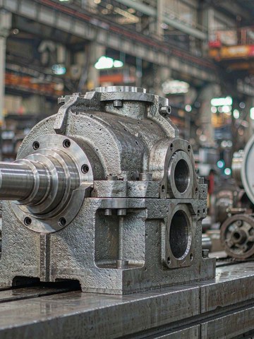
Large energy components are rarely machined from solid. A gearbox housing is cast, a tower bracket is welded, a nacelle frame is a weldment, and a tracker beam is extruded or roll formed. Each of those starting conditions brings distortion into the machine, and the machining plan has to account for it before the first cut.
For weldments, stress relief before finish machining is not optional. Welding locks in residual stress that is released when material is removed, so a bracket that is machined and then welded will move, and a bracket that is welded, stress relieved and then machined will stay where the machine put it. The specification should say which of those sequences applies, because the difference in cost is real and the difference in outcome is larger.
For castings, the first operation is about establishing a datum that exists on every part. Cast surfaces vary by a millimetre or two between pours, so locating on a cast face transfers that variation into the machined features. The usual approach is to probe the casting, establish a best fit datum from the surfaces that matter, and machine from that. On a large housing this is done on the machine itself, with the probe results feeding the program offsets rather than a separate layout step, which is one of the reasons the work runs on five axis centers.
Temperature control closes the loop. A 1.5 m casting moves about 18 micrometres per kelvin, so a shop that is 8 degrees warmer in the afternoon than in the morning is chasing a 0.15 mm drift across a shift. Finish machining and final inspection happen in the same controlled envelope, and the CMM report states the part temperature at measurement, so the customer can judge the number instead of accepting it.
| Component | Typical size | Critical feature | Verification |
|---|---|---|---|
| Main bearing housing | 0.8 to 2 m | Bore H7, shoulder squareness 0.01, coaxiality 0.03 | CMM with common datum, report as a pair |
| Gearbox mounting face | 0.5 to 1.5 m | Flatness 0.05, hole position 0.1 | CMM plus functional gauge on the hole pattern |
| Pitch bearing seat | 0.6 to 1.2 m | Flatness 0.05 over the face, runout 0.08 | CMM, checked relaxed after unclamping |
| Tracker pillow block | 150 to 400 mm | Bore H7, bore to base height within 0.05 | CMM, height checked as a stack not as a single dimension |
| Torque tube end plate | 100 to 300 mm | Bolt pattern position 0.15, face squareness 0.05 | CMM plus trial assembly on a sample |
5. Where Does Prototyping Fit in a Twenty Year Program?
Energy projects move in two speeds. Development is slow and iterative, with a handful of test articles that must be right for the data to mean anything. Deployment is fast and volume driven, with a factory that has to produce hundreds of identical units on a schedule tied to a commissioning date. A supplier who can only do one of those two things forces the customer to manage a transition, and transitions are where tolerances drift.
The machining answer is to build the prototype on the same process route that production will use, at the same fixturing and with the same inspection plan, so that the first article of the production batch is a confirmation rather than a surprise. That sometimes means accepting a slower or more expensive prototype than a quick turn shop would deliver, and it is usually the right trade, because a test article made on a different route tells you about a part you will never build again.
For the volumes involved, our CNC machining and turn mill cells are set up for repeat batches with fixture retention, and the ISO 9001 process documentation is the same for a five piece prototype and a five thousand piece call off. For the vehicle side of the same sector, the material and tolerance logic differs, as our EV parts guide explains. The point is not the certificate on the wall, it is that the inspection record for the prototype can be compared with the record for the production batch.
6. What Should You Send With the RFQ?
Energy RFQs carry more context than most, and the quote is only as good as that context. The useful package includes the drawing set with tolerance and finish callouts, the assembly drawing or at least a description of what the part mates with, the coating specification including the standard it references, the weld map and stress relief requirement for weldments, the annual volume with the ramp shape, and the destination climate for anything that will be shipped and stored before installation.
Two questions are worth answering in advance because they change the process route. Is the part safety related, and does that bring additional documentation such as material traceability to EN 10204 3.1 and a first article inspection to AS9102 or an equivalent? And is there a serialisation requirement, because laser marking a serial into a machined face after finishing is a different operation than marking it before the final pass.
Send that package and a quote is back within 24 hours, with the process route stated so you can compare it against your own assumptions. Where a casting, a weldment or a different material would serve better at your volume, the quote says so.
Frequently Asked Questions
What tolerance can you hold on a large bearing housing?
Plus or minus 0.005 mm is our standard machining tolerance, applied per feature. On housings above half a metre, coaxiality and squareness across the part usually govern rather than the diameter, and we report them against a common datum on the CMM.
Can you machine parts that will be hot dip galvanized afterwards?
Yes. The drawing needs to state which features must remain free of zinc, and tapped holes are either masked or cut after coating. We normally machine a thread undersize and tap after galvanizing when the thread is a primary interface.
How do you handle a weldment that distorts?
By machining after stress relief, and by probing the weldment on the machine to establish a datum from the surfaces that matter. If distortion is large enough that cleanup is at risk, we report it before cutting rather than after.
Do you machine both aluminum tracker parts and steel drivetrain parts?
Yes. Aluminum and steel are machined on separate documented routes with dedicated tooling and separate cleaning, so a mixed order stays under one purchase order and one inspection standard without cross contamination of chips.
What documentation comes with an energy part?
Inspection report with measured values, material certificate traceable to heat number, coating or passivation record where applicable, and a first article report when the drawing or the customer requires one.
How fast can you quote?
Within 24 hours for a complete drawing package. Large weldments and castings that need a datum study sometimes take an extra exchange, because the quote depends on how much cleanup the casting allows.
This article is general engineering guidance, not a binding offer. Tolerances, cost and lead time depend on part geometry, material, quantity and the drawing package you release. Request a quotation for part specific terms. (c) 2026 KGL Machining & Electronics, Shenzhen.
Related Articles
More from the New Energy & EV series.
Have a project in mind?
Send drawings to kgl@kglmfc.com or request a quote. We respond within 24 hours.
Request a Quote