5-Axis CNC Machined Turbine Housing and Stator Vane Assembly
How KGL machines thin-walled turbine housings with integrated stator vanes on 5-axis centers. Radial ports and internal vanes finished in one setup, coaxiality within 0.005 mm.
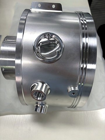
A turbine housing is a thin-walled cylinder with internal aerodynamic guide vanes, radial ports at several angles, and sealing grooves that all interact. Move the part between machines and each new clamping adds runout that is hard to remove later. At KGL we machine housings like this on simultaneous 5-axis centers in one setup, holding coaxiality and cylindricity within 0.005 mm. This article explains why one setup matters so much and how we keep the geometry stable.
Why re-fixturing destroys this part
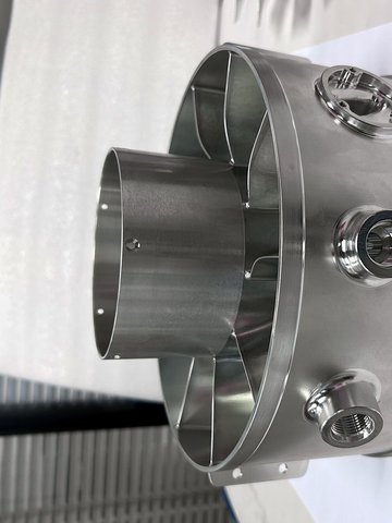
Three features punish a multi-setup route. The internal vane cavities are deep and curved, so handheld tools cannot validate their profile. The outer wall is thin, which means clamping force deforms it before any cutting starts. And the radial ports sit at different angles around the cylinder, so each one used to demand its own fixture orientation.
Every unclamp and reclamp introduces positional error. On a housing where the vanes must stay true to the outer cylinder axis, that error lands directly on the aerodynamic geometry. The only clean answer is to machine all features from one coordinate origin.
One setup, one origin
Continuous five-axis motion machines the internal vanes while keeping the tool in contact with thin sections, so surface continuity does not break. Then 3+2 axis positioning locks the tool at precise angles relative to the outer cylinder, which lets us drill, thread, and counterbore the radial bosses and port flanges in the same cycle.
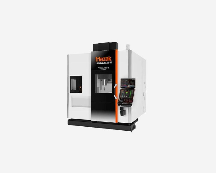
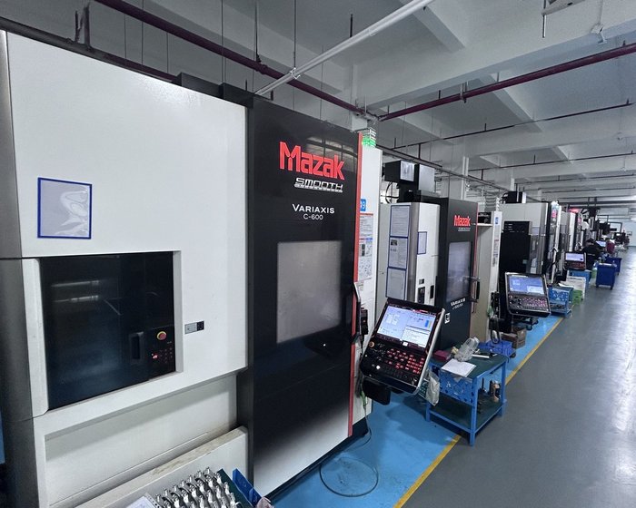
Outer cylinder walls, seal grooves, internal vane profiles, and radial ports all share that single origin. That is what keeps coaxiality, circularity, and perpendicularity tight. We run these programs on Mazak VARIAXIS centers with in-process probing between operations, so offsets are updated before the finishing pass.
Tolerance grades for complex housings
| Attribute | Industry grade | KGL standard | KGL limit |
|---|---|---|---|
| Position tolerance (multi-surface ports) | ±0.3 mm | ±0.015 mm | ±0.005 mm |
| Profile tolerance (curved vanes / GD&T) | ±0.05 mm | ±0.02 mm | ±0.008 mm |
| Coaxiality and cylindricity | ±0.025 mm | ±0.01 mm | ±0.005 mm |
| Angularity and perpendicularity | ±0.03 mm | ±0.015 mm | ±0.005 mm |
| Surface roughness (Ra) | 1.6 μm | 0.8 μm | 0.2 μm |
Inspection is done on CMM and by 3D optical scanning against the customer CAD model, with a full GD&T report for every production lot. The complete program background is in the turbine housing case study.
Materials and applications
We machine turbine housings and stator vane rings from Ti-6Al-4V Grade 5 titanium, Inconel, aluminum 7075-T6 and 6061-T6, and stainless 17-4PH, SUS316L, or SUS304. PEEK and POM appear where the housing carries non-metallic guide or seal elements.
Typical end uses include turbine housings, stator vane rings, auxiliary power units, rocket propulsion components, and high-pressure pump housings. Aerospace customers also find the same one-setup logic in our aerospace machining work.
How we machine it: the 7075-T6 route on the floor
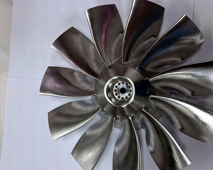
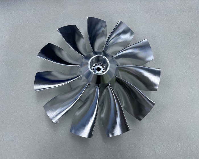
The sample parts are 7075-T6 aerospace aluminum, and the route is simple to state and hard to run: multiple roughing passes, multiple aging steps, then finishing. Roughing uses dynamic milling to strip the bulk of the stock quickly while keeping cutting forces low enough that the thin walls do not spring. Before finishing, we hold the shop at constant temperature and re-verify the machine geometry, because ambient drift of a few tenths is enough to move a thin-walled housing.
The final surfaces are cut on a Mazak VARIAXIS C-600 five-axis center with layered simultaneous milling. One machine, one setup, and the last tool path lands the part on final tolerance.
How the customer program ran
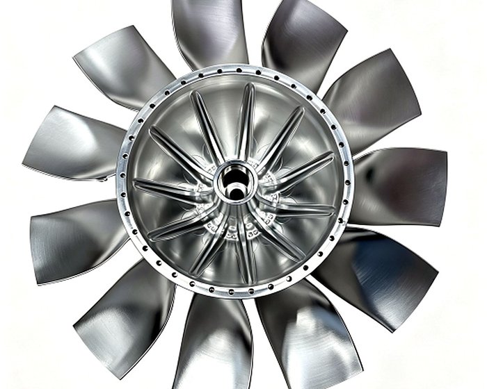
These parts fly in a civil micro-turbofan turbine system. Before shipment every part goes through full-dimension inspection: CMM for size and position, 3D scanning for the vane contour profile, and an added dynamic balancing test on the rotating assembly.
The customer compared our inspection data against their own measurements and found the two data sets closely matched. They accepted our data as the baseline, and the sample approval and mass-production release both went through in a single pass, with no rework loop.
Frequently asked questions
Can the housing and the stator vanes really be finished in one clamping?
Yes. Continuous 5-axis motion reaches the internal vane profiles, and 3+2 positioning handles the radial bosses, in one clamping. Sharing one origin is exactly what holds coaxiality and cylindricity within 0.005 mm.
How do you verify internal vane geometry?
CMM and 3D optical scanning map the vanes against the customer CAD model. Every production lot receives a GD&T report, and first articles get full FAI documentation.
What wall thickness can you hold on a thin cylindrical housing?
Thin-wall stability depends on the envelope, material, and feature layout. Send the drawing and we will confirm the minimum wall we can hold without distortion on your specific part.
Send the drawing
If you have a turbine housing, stator vane ring, or high-pressure pump housing that needs tight coaxiality, send your STEP/IGES models and 2D drawings to kgl@kglmfc.com. We will review the geometry and return a process assessment and quote within 24 hours.
Related Articles
More from the 5-Axis CNC Machining series.
Have a project in mind?
Send drawings to kgl@kglmfc.com or request a quote. We respond within 24 hours.
Request a Quote