GD&T Basics: The 14 Geometric Characteristics Every CNC Buyer Should Know
A practical introduction to GD&T for buyers and engineers: the 14 geometric characteristics, what each symbol means, and how to read a feature control frame on a CNC machined part drawing.
Key Takeaways
- GD&T replaces ambiguous notes like 'true position' with inspectable symbols and datum references that both the machinist and the CMM programmer can read the same way.
- The 14 characteristics fall into five groups: form, orientation, location, runout, and profile. Each group answers a different question about the geometry.
- A feature control frame has four compartments: the characteristic symbol, the tolerance value, the datum references, and any modifiers. Missing any one of them makes the callout incomplete.
- Maximum Material Condition (MMC) and Least Material Condition (LMC) are not academic concepts; they are the reason a pin at its largest size can still pass a position tolerance that would fail it at its smallest size.
- If a drawing mixes plus/minus tolerances with GD&T on the same feature, the tighter requirement wins. The safest route is to convert the whole drawing to GD&T and retire the old limit dimensions.
Most drawings that land on a CNC programmer's desk still carry plus/minus tolerances. They work for simple parts, but once a feature has more than one relationship to worry about, a limit dimension becomes a guessing game. GD&T was created to remove that guesswork. It gives every geometric requirement a symbol, a tolerance zone, and a set of datums that everyone, from the buyer to the inspector, can read the same way.
This article is the first in a short series. It covers the 14 geometric characteristics, what each symbol means, and how a feature control frame is built. Later posts will cover datum selection, MMC and bonus tolerance, and how to set up a CMM program so the reported numbers match the drawing. For the numeric tolerance tables behind this article, the tolerance and fit reference page lists ISO 286 fits, IT grades, and basic deviation values.
1. What GD&T is, and what it replaces
Geometric Dimensioning and Tolerancing is a symbolic language. Instead of writing "hole must be perpendicular to face A within 0.05 mm", you draw a perpendicularity symbol, a tolerance value, and a datum reference. The result is unambiguous, language-independent, and directly translatable into a CMM inspection routine.
The standard that governs this language is ISO 1101, with national equivalents including GB/T 1182-2008. The symbols are the same across standards, which is why a drawing toleranced in GD&T can be quoted by a shop in Shenzhen, machined in Stuttgart, and inspected in Detroit without reinterpretation.
2. The five groups of geometric characteristics
The 14 characteristics are organised into five groups. Each group answers a different question.
| Group | Question it answers | Characteristics |
|---|---|---|
| Form | Does the feature have the right shape by itself? | Straightness, flatness, circularity, cylindricity |
| Orientation | Does the feature point the right way relative to something else? | Perpendicularity, parallelism, angularity |
| Location | Is the feature in the right place? | Position, concentricity, symmetry |
| Runout | Does the feature stay within a band when it rotates? | Circular runout, total runout |
| Profile | Does the surface follow the intended curve or line? | Profile of a line, profile of a surface |
3. Form: the feature on its own
Form controls do not reference a datum. They describe how much a single feature is allowed to deviate from perfect geometry.
3.1 Straightness
Straightness limits how much a line element, either on a surface or along an axis, may bend. On a shaft, an axis straightness callout means the centreline must stay inside a cylindrical tolerance zone. On a flat face, it means any line traced across that face must stay within two parallel lines separated by the tolerance value.
3.2 Flatness
Flatness controls how much a surface may deviate from a perfect plane. The tolerance zone is two parallel planes separated by the stated value. Every point on the surface must fall between them. Flatness is often called out on mounting faces, sealing surfaces, and fixture bases.
3.3 Circularity
Circularity, also called roundness, limits how much a cross-sectional element may deviate from a perfect circle. The tolerance zone is two concentric circles separated radially by the tolerance value. It is inspected on a single slice, not along the length of the feature.
3.4 Cylindricity
Cylindricity is the three-dimensional extension of circularity. It controls roundness, straightness, and taper at the same time. The tolerance zone is two coaxial cylinders separated radially by the tolerance value. It is one of the most expensive callouts to inspect because it requires scanning the full surface, but it is essential for bearing seats and precision bores.
4. Orientation: direction relative to a datum
Orientation controls always reference a datum. They answer the question: does this feature point the right way compared to something I trust?
4.1 Perpendicularity
Perpendicularity limits how far a feature may deviate from 90 degrees relative to a datum. On a hole, it means the axis must stay inside a cylindrical tolerance zone oriented perpendicular to the datum face. On a planar face, it means the face must stay between two parallel planes perpendicular to the datum.
4.2 Parallelism
Parallelism limits how far a feature may deviate from parallel relative to a datum. The tolerance zone is two planes or lines parallel to the datum, separated by the tolerance value. It is commonly used on rails, guide surfaces, and mating faces that must slide against each other.
4.3 Angularity
Angularity controls any angle other than 90 degrees. The tolerance zone is two planes or lines at the stated basic angle, separated by the tolerance value. The basic angle is given in a box next to the feature control frame and is theoretically exact, meaning it has no tolerance of its own.
5. Location: where the feature belongs
Location controls are the reason most buyers first encounter GD&T. They answer the question: is the hole, slot, or boss in the right place?
5.1 Position
Position is the most powerful location control. It defines a tolerance zone, usually a cylinder or a pair of parallel planes, centred on the theoretically exact location given by basic dimensions. The actual feature axis or centre plane must fall inside that zone.
The real economy of position tolerance comes from modifiers. At Maximum Material Condition (MMC), the tolerance zone grows if the feature is produced at a size that gives it more clearance. A hole at its smallest size gets the stated tolerance; a hole at its largest size gets a bonus tolerance equal to the difference. The same logic applies to shafts, but in reverse. This is why a position callout with an MMC modifier can accept parts that a plain plus/minus tolerance would reject.
5.2 Concentricity
Concentricity controls the median points of a feature relative to a datum axis. It is stricter than position because it evaluates the distribution of material, not just the axis location. For most practical parts, position with an MMC modifier is sufficient and far easier to inspect. Concentricity is reserved for high-speed rotating parts where mass balance matters.
5.3 Symmetry
Symmetry controls how far the median plane of a feature may deviate from the median plane of a datum. It is rarely used in modern practice because position, with the correct datum structure, usually covers the same requirement more cleanly. It appears on legacy drawings and some forging and casting standards.
6. Runout: control during rotation
Runout controls are composite: they limit form, orientation, and location at the same time, but only while the part rotates about a datum axis. They are the standard control for shafts, flanges, and any part that spins.
6.1 Circular runout
Circular runout is evaluated at a single cross-section. The indicator is held stationary axially while the part rotates. The total indicator reading must not exceed the tolerance value. It controls roundness and concentricity at that slice, but not along the length.
6.2 Total runout
Total runout is evaluated along the full length of the feature. The indicator moves axially while the part rotates, or the part moves axially while the indicator stays still. The total indicator reading must not exceed the tolerance value anywhere along the sweep. It is the strictest runout control and is used for bearing journals and seal surfaces.
7. Profile: following the intended shape
Profile controls are the most flexible in GD&T. They can control any curve or surface, and they can be referenced to datums or left free-floating.
7.1 Profile of a line
Profile of a line controls the shape of a line element in a single cross-section. The tolerance zone is two lines that follow the theoretically exact profile, separated by the tolerance value. It is used for cam profiles, seal grooves, and any feature where the two-dimensional contour matters.
7.2 Profile of a surface
Profile of a surface is the three-dimensional extension. The tolerance zone is two surfaces that follow the theoretically exact profile, separated by the tolerance value. Every point on the actual surface must fall between them. It is used for turbine blades, mould cavities, and any complex sculpted surface.
8. How to read a feature control frame
The feature control frame is the box that carries the GD&T requirement. It is read from left to right and has up to four compartments.
| Compartment | What it contains | Example |
|---|---|---|
| 1 | The geometric characteristic symbol | Position symbol |
| 2 | The tolerance value, sometimes with a diameter symbol and a modifier | 0.05 with diameter symbol and MMC circle M |
| 3 | The primary datum reference | A |
| 4 | The secondary and tertiary datum references, if needed | B, C |
A complete callout looks like this: a position symbol, followed by 0.05 with a diameter symbol and an MMC modifier, followed by datum A, then datum B, then datum C. This means the feature axis must stay inside a cylindrical zone of diameter 0.05 mm, perpendicular to datum A, positioned relative to datums B and C, and the tolerance zone grows if the feature is at MMC.
9. Modifiers: MMC, LMC, and projected tolerance zone
Modifiers change the size of the tolerance zone based on the actual produced size of the feature.
Maximum Material Condition (MMC) means the condition where the feature contains the most material within its size limits. For a hole, that is the smallest diameter. For a shaft, that is the largest diameter. When MMC is applied to a position tolerance, the stated tolerance applies at MMC, and a bonus equal to the departure from MMC is added. This is the mathematical basis for functional gauging: a go gauge at virtual condition will accept every part that the GD&T callout accepts.
Least Material Condition (LMC) is the opposite: the condition with the least material. For a hole, that is the largest diameter. It is used for wall thickness and minimum distance requirements, where the concern is not fit but structural integrity.
Projected tolerance zone is used for threaded holes and press-fit studs. The tolerance zone is projected above the surface by the length of the fastener or insert, so the position tolerance controls the alignment of the assembled feature, not just the hole itself.
10. When to use GD&T on a CNC drawing
GD&T is not mandatory for every part. A simple bracket with two holes and a flat face is often faster to tolerance with plus/minus limits. The switch to GD&T pays off when any of the following are true.
- The part has more than one datum relationship that matters. A bore that must be perpendicular to a face, concentric to a pilot diameter, and positioned relative to a bolt pattern cannot be described cleanly with limit dimensions.
- The part will be inspected on a CMM. GD&T callouts map directly to CMM software features. Plus/minus tolerances require manual interpretation.
- The part is part of an assembly where fit is controlled by functional gauges. GD&T with MMC is the language that connects the drawing to the gauge design.
- The buyer and the supplier are in different countries. GD&T symbols are universal; written notes are not.
Our capabilities page lists the CMM and optical inspection equipment we use to verify GD&T callouts, and our equipment page shows the machines that produce the geometric accuracy those callouts demand.
11. Common mistakes buyers make
| Mistake | Why it hurts | How to fix it |
|---|---|---|
| Mixing plus/minus and GD&T on the same feature | The tighter requirement wins, but the machinist may not know which one the inspector will enforce | Convert the whole drawing to GD&T and remove the redundant limit dimensions |
| Calling out concentricity when position is enough | Concentricity is harder to inspect and often adds cost without functional benefit | Use position with MMC unless mass balance is critical |
| Missing datum references | The tolerance zone has no anchor; the inspector has to guess which face is primary | Always list primary, secondary, and tertiary datums in order of functional importance |
| Over-tolerancing form on a feature that also has orientation or location | A tight flatness on a face that also has perpendicularity is usually redundant; the orientation control already limits the form | Let the orientation or location control carry the requirement unless form is independently critical |
| Forgetting the modifier on a clearance hole | Without MMC, every hole must meet the full position tolerance regardless of size, which rejects functionally good parts | Add the MMC modifier to position tolerances on clearance features |
12. From drawing to CMM program
The final step is turning the drawing into numbers. A CMM program for a GD&T part follows the datum structure: establish the primary datum as a plane, the secondary as a line or axis, and the tertiary as a point or intersecting feature. Then measure the toleranced feature and report its deviation from the theoretically exact position or orientation.
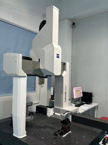
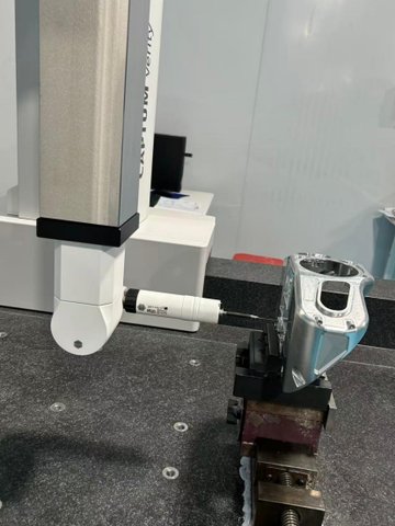
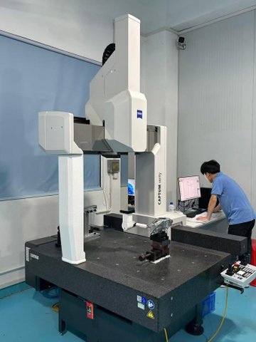
The photos below show our CMM inspection environment: the bridge CMM itself, the probe in contact with a machined housing, and the inspection bay where the operator runs the routine. The probe path follows the datum structure on the drawing, and the report lists each characteristic with its measured value, tolerance, and pass or fail status.
Frequently Asked Questions
What is the difference between GD&T and plus/minus tolerancing?
Plus/minus tolerancing limits the size of a feature. GD&T limits the geometry, orientation, and location of a feature relative to datums. A hole can be within its diameter limits but still be out of position, out of perpendicularity, or out of roundness. GD&T captures all of those requirements in one symbolic language.
Do I need GD&T for every CNC part?
No. Simple parts with one or two features are often faster to tolerance with plus/minus limits. GD&T becomes valuable when a feature has multiple relationships to other features, when the part will be inspected on a CMM, or when the drawing must be understood across languages and suppliers.
What is a datum, and how do I choose it?
A datum is a theoretically exact reference feature that anchors the rest of the geometry. The primary datum is usually the face that mounts the part to the next assembly. The secondary datum is a feature that controls orientation, such as a bore or an edge. The tertiary datum locates the part in the final degree of freedom. Datum selection is covered in the next article in this series.
What does MMC mean in practice?
Maximum Material Condition means the tolerance zone grows if the feature is produced at a size that gives it more clearance. A hole at its smallest size gets the stated position tolerance. A hole at its largest size gets a bonus tolerance equal to the size difference. This allows functional gauges and reduces rejections of parts that still assemble correctly.
Can KGL inspect GD&T callouts on my parts?
Yes. We use CMMs with GD&T software modules that read the feature control frame directly. The CMM program is built from the drawing datums and characteristics, and the report lists each measured value with its tolerance and pass or fail status. Send the drawing with the GD&T callouts and we will confirm the inspection route at quotation.
Which GD&T standard should I use?
ISO 1101 is the international standard and is equivalent to ASME Y14.5 in the United States and GB/T 1182-2008 in China. The symbols are the same across all three. If your customer specifies a standard, use that one. If not, ISO 1101 is the safest default for international supply chains.
This article is general engineering guidance, not a binding manufacturing guarantee. Tolerance specifications, inspection methods, and CMM reporting formats are confirmed per part based on drawings, materials, quantities, and process review. Request a formal quotation for part-specific terms. (c) 2026 KGL. All rights reserved.
Related Articles
More from the Inspection & Metrology series.

Have a project in mind?
Send drawings to kgl@kglmfc.com or request a quote. We respond within 24 hours.
Request a Quote