How to Read a Feature Control Frame (and What a CNC Shop Actually Measures)
A feature control frame is read left to right and it answers three questions: what to control, how much, and against what. Here is the frame cell by cell, the modifiers that change the pass limit, a worked reading of a real frame, and what a shop actually measures for each one.
Key Takeaways
- A feature control frame is read left to right: the geometric symbol says what to control, the value and its modifiers say how much, and the datum letters say what to control it against.
- Datum letters are read in order, and the order is a measurement instruction, not decoration. The first datum is the primary seating surface, so the frame usually mirrors the way the part is assembled.
- A diameter sign on the tolerance value means the zone is cylindrical rather than two parallel planes. Dropping it changes the zone shape and can change a pass into a fail.
- The material condition modifier M turns the stated value into a floor. As the feature departs from maximum material, the allowed tolerance grows by the same amount, so the inspector has to measure the actual size before the position result means anything.
- A composite frame is two frames stacked. The upper tier locates the pattern as a group, and the lower tier controls each feature relative to the others in that group.
- Reading the frame is only half the job. The other half is knowing what the shop has to measure to satisfy it, and whether the drawing says enough for the inspection plan to be built without a phone call.
Most sourcing problems that look like quality problems start as reading problems. A frame gets skimmed, the diameter sign or the material modifier is missed, and the part is quoted, made and inspected against a tolerance that is not the one the drawing asked for. The frame itself is short, usually three or four cells, and it rewards two minutes of proper reading.
This is the closing article in our GD&T series, after form, orientation, location and runout tolerances. It takes the frame apart cell by cell, explains the modifiers that change where the pass line sits, and finishes with what a shop has to measure to satisfy each callout.
1. Where a feature control frame sits on a drawing
A feature control frame is the rectangular box divided into cells that is attached to a feature by a leader line. It is not a note and it is not a general tolerance. It is a compact instruction about one specific feature, and it overrides whatever the general tolerance block would otherwise allow for that feature.
Frames are attached either to a size dimension, when the control applies to the feature of size, or directly to a surface or an extension line, when the control applies to a face. A frame with one leader arrow points at a single feature. A frame with two arrows, or a frame placed between two dimension lines, applies to a pattern. That distinction matters before anything else in the frame is read, because a position callout on a hole pattern is judged as a group, not hole by hole.
The frame can also carry a note above or below it, such as a quantity of features, a between statement that fixes the extent of the control, or a note about the state of the part during measurement. Those notes are part of the requirement and are easy to lose when a drawing is photographed or scaled down.
2. The three cells, in reading order
Read the frame left to right and it answers three questions in sequence. What is being controlled. How much is allowed. Against what reference.
Everything else on a drawing is support for those three cells. The section view shows where the feature is. The basic dimensions, the ones in boxes, say where it is supposed to be. The datum feature symbols identify the surfaces the frame refers to. None of it changes the reading order, and none of it can be skipped.
3. Cell one: the geometric symbol
The first cell holds one symbol, and that symbol selects which of the fourteen geometric characteristics applies. It is the whole content of the cell and there is nothing to interpret beyond recognising it.
One practical consequence follows from this. Because the symbol fixes the type of control, it also fixes the shape of the tolerance zone, and that is what most suppliers are really being told. A flatness symbol means two parallel planes. A circularity symbol means two concentric circles at one section. A position symbol means a zone centred on a theoretically exact location, and if it carries a diameter sign that zone is a cylinder. Two callouts with the same numeric value but different symbols are not equivalent, and a quote that treats them as equivalent will not survive inspection.
The symbol also decides which datum letters may appear in the last cell. Form tolerances get no datum letters at all, because a form control compares the feature to itself. Orientation and location and runout controls take one or more datum letters, because they compare the feature to something else. If a frame shows a flatness symbol with a datum letter after it, that is a drafting error, and it is worth flagging before the drawing goes to a supplier rather than after a part is rejected.
4. Cell two: the tolerance value and its modifiers
The second cell carries the numeric value, and around that value sit the small marks that change what the number means. There are five worth knowing well.
The diameter sign before the value, written as a circle with a slash through it, means the tolerance zone is cylindrical rather than two parallel planes. It is used with controls that apply to an axis or a centre plane, such as position, coaxiality and perpendicularity on a hole. It is not decoration. A position callout of 0.1 without a diameter sign allows a rectangular zone, and a part can pass that rectangular zone and fail a cylindrical one of the same value, because the corners of the rectangle sit further from the true position than the value allows in a round zone.
The M in a circle is the maximum material condition modifier. It converts the stated value into a floor rather than a fixed limit. As the actual feature departs from its maximum material size, the permitted geometric tolerance grows by exactly that departure. A hole made at its smallest allowed size is at maximum material and gets only the value in the frame. A hole made at its largest allowed size gets the value plus the whole size range. This is the modifier that most often turns an argument into a measurement, because the pass limit depends on the measured size of the feature, not only on where it sits.
The L in a circle is the same idea in the other direction, applied at least material condition, and it is used where the function depends on the minimum wall rather than on assembly clearance. S in a circle means regardless of feature size, which is the default and means the geometric tolerance is fixed no matter what size the feature ends up being.
The last pair are the tangential and free state notes. A T means the control applies to a tangent plane resting on the high points rather than to the surface itself, which is used where a mating face bears only on its high spots. An F means the requirement applies to the part in its free state, before any clamping, which matters on thin or flexible parts that spring when they come out of the fixture.
5. Cell three: the datum reference letters
The third cell lists the datum features in order, usually three of them separated by dividers. Read them in the order written and the meaning is fixed: the first is primary, the second is secondary, the third is tertiary.
This order is a measurement instruction, and it is also a statement about assembly. A part seated on face A, pushed against face B and stopped on face C during assembly has to be measured the same way, or the inspection and the application are describing two different parts. A supplier who sets the part up on the secondary face and probes the primary will report a different number from a supplier who follows the frame, and both will believe they are right.
The 3-2-1 rule describes why three datums is the usual number. A primary plane removes three degrees of freedom, a secondary plane removes two, and a tertiary removes the last one. Where a frame lists a common datum, written as two letters with a divider, it means the two surfaces act together as one datum, which is what happens on a split bearing housing or a pair of pads machined in one pass. Where a frame carries an M after a datum letter, the datum feature itself is at maximum material during the check, and the datum simulator is the smallest size that will still fit the feature.
6. Composite frames, and what the second tier does
Two frames stacked and joined at the left form a composite frame, and the cells line up between the tiers. The upper tier is a pattern locating control and the lower tier is a feature relating control.
The upper tier fixes the pattern as a group relative to the datums. The lower tier fixes each feature relative to the other features in the same pattern, using the same datums but with tighter practical effect, because it does not carry the location allowance of the upper tier. On a plate with six holes, this is the difference between asking whether the whole pattern sits in the right place and asking whether the holes are spaced correctly inside themselves. A shop that treats a composite frame as one requirement will inspect the wrong thing twice, which is why the tier is worth pointing at during quoting.
7. Supplementary symbols worth knowing
Beyond the modifiers inside the tolerance cell, a few other marks appear often enough to be worth a reference row. The table below is the one we keep to hand when a drawing is being reviewed for quotations.
| Mark | Where it sits | What it means in practice |
|---|---|---|
| Diameter sign | Before the tolerance value | The zone is cylindrical, centred on the true position or the datum axis, rather than two parallel planes |
| M in a circle | After the tolerance value, or after a datum letter | The tolerance is a floor that grows as the feature departs from maximum material; after a datum letter it sets the datum simulator size |
| L in a circle | After the tolerance value | The same mechanism applied at least material condition, used where minimum wall governs instead of assembly clearance |
| S in a circle | After the tolerance value | The geometric tolerance is fixed regardless of feature size, which is the default behaviour |
| P in a circle | After the tolerance value | Projected tolerance zone, applied where a pin or bolt crosses a gap after the hole, so the zone extends beyond the feature |
| T in a circle | After the tolerance value | The control applies to a tangent plane on the high points rather than to the surface itself |
| F in a circle | After the tolerance value | The requirement applies in the free state, before clamping, which matters on flexible parts |
| CZ | After the tolerance value | Common zone, so the stated zone is shared across several features rather than applied to each of them separately |
| Two separated letters | In the datum cell | A common datum, so the two surfaces act as one reference and are established together |
| Stacked frames | Whole frame | A composite requirement, upper tier locating the pattern and lower tier relating the features within it |
The point of the table is not to memorise it. It is to notice how much of a frame can change the pass limit without changing the number in it, which is why a frame is quoted from the whole box and never from the value alone.
8. Reading a frame end to end
Here is the walkthrough we use when a drawing is being reviewed for a quotation, based on a schematic drawing rather than a customer file. Take a rectangular aluminium plate with a pattern of four holes for locating dowels, and one frame attached to the pattern.
Start with the leader. Two arrows or a frame between dimension lines means the control applies to the pattern as a group. Next the symbol, which is position, so the requirement is about where the holes are rather than how round or how straight they are. Next the tolerance cell, which reads as a diameter sign followed by 0.1 and then M, so the zone is a cylinder 0.1 in diameter and that value grows as the holes run above their minimum size. Last the datum cell, which lists three letters, so the whole pattern is located from a primary seating face, a secondary face and a tertiary stop, in that order.
The reading obtained is complete enough to price the job. It says the shop has to control the seating face and the two locating features to the stated datum scheme, it says the holes are judged as a pattern, and it says the position result depends on the measured size of each hole because of the material modifier. That last point is the one that decides whether the inspection plan is a simple gauge check or a full CMM routine, and it is the point most often missed when a frame is read quickly.
Now change one thing. Remove the M and the value becomes a fixed limit, so every hole is judged against 0.1 no matter what size it comes out. Keep the M and the same holes, at the top of their size range, may pass with a position error well above 0.1. Same drawing, same number, two different acceptance rules. This is the single most valuable habit in reading frames: check the modifiers before reading the number.
9. What a CNC shop actually measures for each callout
A frame tells the shop what to control. It does not tell the shop how, and the how is where a quotation either holds or drifts. The list below is how the work is usually planned in a shop that runs the inspection in house.
| Callout | Usual method in the shop | What the report carries |
|---|---|---|
| Flatness, straightness | Surface plate and indicator, or a CMM plane fit across a grid of points | Highest and lowest deviation, and the resulting value against the zone |
| Circularity, cylindricity | Roundness instrument, or a CMM with multiple sections and a least squares fit | Per section value and the worst section, plus the fitting method used |
| Perpendicularity, parallelism, angularity | CMM with the datum features probed first, in the order the frame states | Measured deviation and the datum scheme actually used |
| Position, coaxiality, symmetry | CMM, true position calculated from the measured axis against the basic dimensions | Actual size of the feature, the position error, the bonus applied and the pass limit after the bonus |
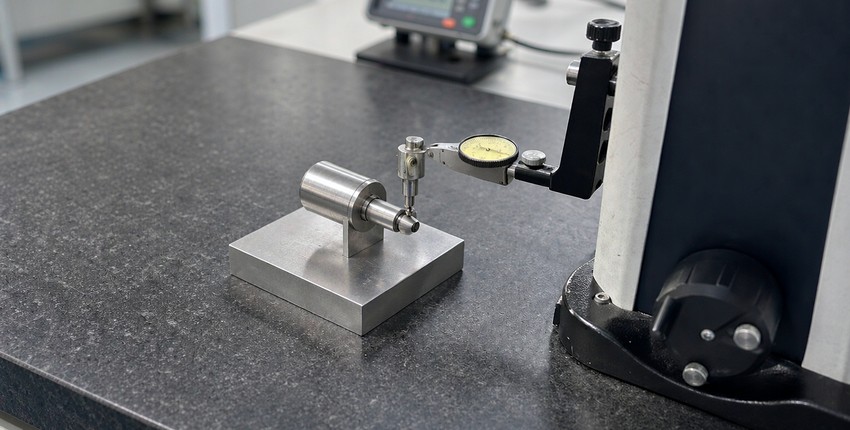
| Runout | Bench centres or a V block with a lever gauge, escalating to a CMM with a rotary table | Highest and lowest reading, the runout value and the percentage of the zone consumed |
Two habits make this work in practice. The first is that the datum features are probed before the toleranced features, in the order the frame gives, so the reference is established rather than assumed. The second is that the report states the zone consumed as a percentage, not only pass or fail. A part that ships at 90 percent of its allowance is a different risk from one that ships at 30 percent, and the customer cannot see the difference from a pass stamp. The same reporting discipline is described in our article on first article inspection, and the equipment behind it is listed on the inspection equipment page.
It is also worth saying what a frame cannot do. It cannot rescue a drawing that leaves the datum scheme ambiguous, and it cannot fix a basic dimension that contradicts a general one. Those are drawing problems, and they are cheaper to settle at quotation than after a first article.
10. Sending a drawing to China: the frames worth flagging
For a buyer sending a drawing to a supplier overseas, four frame situations are worth calling out explicitly in the request, because each one changes the price or the inspection time.
A frame with a material modifier is the first. It tells the supplier the pass limit depends on the measured size of the feature, so the inspection has to record sizes and not only positions. A composite frame is the second, because it means two separate requirements are stacked in one box. A frame that references a datum established by the customer during assembly, such as a face that is later welded or pressed, is the third, because the supplier has to know how that datum is simulated on a loose part. And a frame with a tolerance tighter than about 0.01 mm is the fourth, because at that level the measuring uncertainty of the check itself has to be stated, and the shop will need to know it before it can commit.
None of those are problems. Each is a question with an answer, and asking it before the order is placed moves the answer to the cheapest possible point in the job. A drawing that carries the datum scheme, the basic dimensions and the modifiers will usually be quoted in a day. A drawing that leaves any of the three open will come back as a question, which is slower but still much faster than finding out at first article.
11. The series in one paragraph, and the next step
Across the six articles, the ground covered runs from the fourteen characteristics, through form and orientation and location and runout, to this closing piece on reading a frame. Form tolerances judge a feature against itself and take no datum. Orientation and location compare a feature to a datum, and location is the group that decides whether assemblies fit. Runout bundles form, orientation and location into one rotation based number. Feature control frames are how all of it reaches a shop, and reading them properly, cell by cell and modifier by modifier, is what keeps a quotation and a part and an inspection report saying the same thing.
If a drawing is open on your desk, the practical next step is a review rather than a search. Our engineering reference centre carries the tolerance and material tables we work from, the frame symbols above are the ones that change a pass limit most often, and the equipment list shows what the tolerances are checked on. Send the drawing with the frames and the datum scheme, and the achievable values and the inspection plan come back with the quote.
Frequently Asked Questions
How do you read a feature control frame?
Read it left to right. The first cell holds the geometric symbol, which says what is being controlled. The second holds the tolerance value together with any diameter sign and modifiers, which says how much is allowed and what shape the zone has. The last cell lists the datum features in order, which says what the control is measured against.
What does the M in a circle mean on a drawing?
It is the maximum material condition modifier. It turns the stated geometric tolerance into a floor that grows as the actual feature departs from its maximum material size. A hole at its smallest allowed size gets only the value in the frame, and a hole at its largest allowed size gets that value plus the whole size range. The modifier after a datum letter instead sets the size of the datum simulator.
Why does the order of the datum letters matter?
The order states the sequence in which the datums are established, so it is a measurement instruction as much as a design intent. The primary datum is the surface the part seats on first, and it removes three degrees of freedom. A part that is measured on a different sequence from the one the frame states will produce a different result, even when the part itself is unchanged.
What is a composite feature control frame?
It is two frames stacked and joined at the left edge, with the cells aligned between the tiers. The upper tier locates the pattern as a group relative to the datums. The lower tier relates each feature to the other features in that pattern. Treating the two tiers as one requirement leads to inspecting the wrong thing, so they are worth confirming at quotation.
What does the diameter sign in the tolerance cell change?
It changes the shape of the tolerance zone from two parallel planes to a cylinder centred on the true position or the datum axis. That matters because a rectangular zone permits more error at its corners than a round zone of the same value allows in any direction. Dropping the sign, or adding it, can turn a pass into a fail without the number changing.
Can KGL read frames and build the inspection plan from a drawing?
Yes. Drawings are reviewed at quotation, with the datum scheme, the basic dimensions and the modifiers checked before a price is given. Where a callout affects the inspection plan, that is stated in the quote rather than discovered on the first article. Inspection runs on a Zeiss CAPTUM CMM with the datum features probed in the order the frame gives, and reports state the measured value and the percentage of the zone consumed. Send the drawing with the frames and the datum scheme and we will confirm the achievable values.
This article is general engineering guidance, not a binding manufacturing guarantee. Tolerance feasibility, inspection methods and reporting formats are confirmed per part based on drawings, materials, quantities and process review. Request a formal quotation for part-specific terms. (c) 2026 KGL. All rights reserved.
Related Articles
More from the Inspection & Metrology series.

Have a project in mind?
Send drawings to kgl@kglmfc.com or request a quote. We respond within 24 hours.
Request a Quote