Position, Coaxiality and Symmetry: Location Tolerances That Make Assemblies Fit
How location tolerances work on CNC drawings: the true position formula with a worked example, when to use a diameter zone, coaxiality versus runout, symmetry with a common zone, and how bonus tolerance under MMC changes the pass limit.
Key Takeaways
- Location tolerances control where a feature sits relative to datums. Position is the most used of the three because its cylindrical zone controls location in every direction at once.
- The true position formula compares the measured offset of a feature axis against its basic location: twice the square root of the squared X and Y deviations.
- A position callout with a diameter symbol creates a cylindrical zone; without it the zone is two parallel planes and only one direction is controlled.
- Runout is often the better callout for rotating parts because it is cheaper to verify, but it bundles form, orientation and location into one number and cannot separate them.
- Under MMC, bonus tolerance is added as the feature departs from its maximum material condition, so a hole at its largest allowable size gets a wider position zone while the mating pin still fits.
Form tolerances judge a feature against itself. Orientation tolerances judge a feature against a datum. Location tolerances go one step further: they fix where a feature must sit, relative to a datum system, so that the assembly actually goes together. Of the three location characteristics, position does most of the work on CNC drawings, and it is also the callout that generates the most quoting questions.
This article is the fourth in our GD&T series, after form tolerances and orientation tolerances. It covers the true position formula with a worked example, the choice between position, coaxiality and runout, symmetry with a common zone, and how maximum material condition changes the pass limit at inspection.
1. Why position is the strongest symbol on the drawing
A position callout places the axis or center plane of a feature inside a zone that is located at basic dimensions from the datums. Basic dimensions are exact by definition: they carry no tolerance of their own, because all of the allowed variation lives inside the geometric zone.
When the feature control frame carries a diameter symbol, the zone is a cylinder. The axis of the hole must fall anywhere inside that cylinder and the part is good. That single number bounds the offset in every direction at once, which is exactly what a bolt or a pin needs. Without the diameter symbol, the zone collapses to two parallel planes and the callout only controls one viewing direction, which is rarely what a fastener pattern wants.
That is also why position tolerances are usually more generous than the coordinate tolerances they replace. A typical fastener hole might get a 0.25 mm diameter position zone, while an equivalent coordinate scheme would need tighter X and Y limits to achieve the same assembly guarantee. The zone is shaped like the failure mode.
| Characteristic | Zone | Needs datums | Typical use |
|---|---|---|---|
| Position | Cylinder (with diameter symbol) or two planes | Yes, full datum system | Bolt hole patterns, dowel holes, port faces, pin locations |
| Coaxiality | Cylinder around the datum axis | Yes, one datum axis | Spindle seats, bearing journals, seal diameters |
| Symmetry | Two parallel planes about the datum center plane | Yes, one datum plane | Slots, keyways, opposed features that must straddle a center |
2. The true position formula, worked through
Inspectors and buyers ask for the true position formula more than any other GD&T calculation. It converts a measured offset into a diameter value that can be compared against the zone in the frame.
True position = 2 x sqrt(deviation X squared + deviation Y squared)
The deviations are the differences between the measured feature location and the basic location, in the two datum axes of the measurement plane. Multiplying by two converts a radius into a diameter, so the result compares directly with the diameter zone in the frame.
Worked example. A hole pattern on an aluminum fixture plate calls a hole at basic coordinates 40.000 mm from datum B and 25.000 mm from datum C, inside a 0.10 mm diameter position zone at maximum material condition relative to A, B and C. The CMM reports the actual hole axis at 40.028 mm and 24.961 mm.
The X deviation is 0.028 mm and the Y deviation is minus 0.039 mm. Squared and summed: 0.000784 plus 0.001521 equals 0.002305. The square root is about 0.048 mm, and doubled gives a true position of about 0.096 mm.
At nominal hole size the part passes, because 0.096 mm falls inside the 0.10 mm zone. At the extremes it would fail, and this is where the number earns its keep: the report shows not just pass or fail but how much of the zone the feature has used. A hole consuming 96 percent of its zone on a first article is a warning even when the part ships, because the next batch will not all land in the same spot.
One caution on the arithmetic. The formula assumes the deviations are measured in a coordinate system that is square to the datums and in the same units as the zone. Mixing an X deviation taken along the part edge with a Y deviation taken along a fixture edge is the most common way a shop produces a passing number for a part that does not assemble. The datum alignment is part of the measurement, not a formality.
3. Position, coaxiality and runout: choosing between them
For a single diameter that must run true to a datum axis, three callouts can apply, and they are not interchangeable.
Position on a diameter creates a cylindrical zone around the basic axis. It fixes where the feature axis may sit, but it says nothing about the surface form between the extremes. It is the right callout for a bore that must align with a mating bore, and it is the only one of the three that can carry a bonus under MMC.
Coaxiality also creates a cylindrical zone around the datum axis, and it requires that the median points of the toleranced feature fall inside it. It is stricter in intent than position for the same value, because the evaluation is based on the derived axis over the full feature rather than a single extracted axis. It is also the most expensive of the three to verify properly, since it needs a CMM with the right evaluation algorithm rather than a bench setup.
Runout is a composite control: rotating the part against a datum and reading a dial indicator captures form, orientation and location error together. It is the cheapest rotating-part check there is, and it matches how most rotating parts actually fail in service. The trade is that a failed runout reading does not tell you which of the three error sources caused it. We cover circular versus total runout in the next article of this series.
Our default advice to customers mirrors what we wrote in the supplier red flags article: ask what the callout is protecting. If the requirement is assembly fit, position is right and the diameter symbol belongs in the frame. If the requirement is smooth rotation, runout is right and coaxiality is usually an expensive detour. If a drawing carries coaxiality on a non-rotating part with no functional reason behind it, that is a question worth raising before the quote, not after the first inspection report.
4. Symmetry and the common zone
Symmetry locates the median points of a feature within two parallel planes centered on a datum plane. On machined work it appears most often on slots, keyways and opposed pockets where two halves of a feature must straddle a center plane evenly.
Two practical notes. First, symmetry is measured on median points, not surfaces, so verifying it needs a CMM rather than a dial indicator on the faces. Second, when two or more separated features are toleranced to each other rather than to a datum, the frame is extended with the letters CZ, for common zone. The zones then merge into one continuous region, and the group must fit inside it together. On a pair of opposing slots machined in one setup, a common zone callout is what guarantees the pair stays coherent; machining them in two setups almost guarantees an argument about it.
5. A worked hole-pattern example, and what MMC does to it
Start with a generic pattern to see how the numbers move, then look at a live job in the next section.
Take a valve manifold plate with twelve fastener holes on a 0.20 mm diameter position zone at MMC, relative to A, B and C. The holes are dimensioned 6.5 plus 0.1 minus 0, so maximum material condition is 6.5 mm, the smallest the hole may be.
If the CMM finds a hole at 6.58 mm, the hole has grown 0.08 mm above MMC, and that 0.08 mm is added to the zone as bonus tolerance. The effective pass limit for that hole is now 0.28 mm. The assembly still works, because the extra clearance in the hole diameter is exactly what absorbs the extra axis offset. That is the whole point of the modifier: the pass limit floats with the feature size while the mating condition stays fixed.
Two consequences matter for buyers. First, a position callout at MMC almost never rejects a part that assembles, which is why it is the default on fastener patterns and the reason a quoted part with it should not carry a mystery premium. Second, the modifier must be stated. An identical frame without the MMC symbol holds the zone at 0.20 mm regardless of hole size, and on a twelve-hole pattern that difference can be the gap between a routine job and one that needs sorting to ship.
6. Shop floor case: two 6.7 mm holes on a PTFE support plate
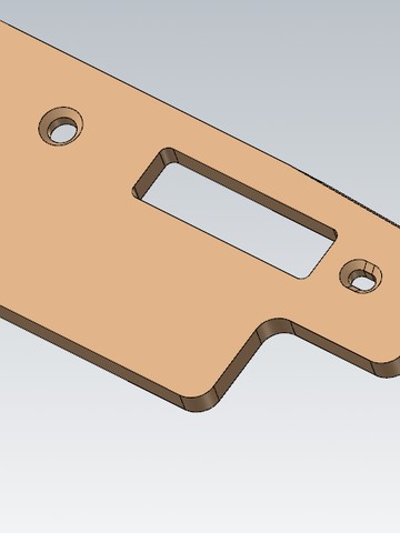
The part below is one we quoted and machined: an insulation support plate in PTFE White for semiconductor process equipment, 186.36 by 60.45 by 5.6 mm. Two 6.7 mm through holes, dimensioned 6.7 plus 0.016 minus 0.004, are held to a 0.02 mm diameter position zone relative to datum B, the plate edge. The 74 mm spacing between the two holes carries plus or minus 0.01 mm, and the drawing asks for a clean break on every sharp edge with no coating.
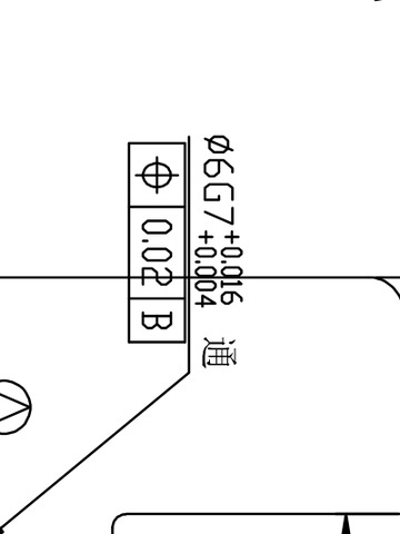
The missing modifier is what settles the process. With MMC in the frame, a hole cut at the top of its range would earn bonus tolerance and the pass limit would float wider than 0.02 mm. Without it, the zone stays at 0.02 mm whatever the hole measures, so diameter and location have to land together, and the inspection record has to carry a position value rather than a functional pass from a gauge alone.
Material sets the second limit. PTFE expands roughly ten times more than aluminium, about 100 to 135 parts per million per degree C. Over the 186 mm length of this plate, a 10 C gap between cutting temperature and measuring temperature moves the material by about 0.2 mm, which is ten times the position zone. No feed rate or tool geometry recovers that. The job is planned around temperature instead: parts and gauges rest in the same controlled room, the tight features are finished in one setup at the end of the cycle, and the CMM runs at 20 C plus or minus 1 C. PTFE also marks easily, so parts are handled with gloves and stay off bare bench tops between operations.
Inspection runs on two tracks. A go and no-go pin gauge sized at the virtual condition screens every part on the floor in seconds, which suits a thin plate where a full CMM cycle per part would not pay. Samples then go to the CMM, where datum A is built from the plate face and datum B from the edge, and each hole is scanned in several sections so the fitted axis describes the bore rather than a few points. The PTFE machining page covers the material side, and the same datum discipline carries through our semiconductor parts work.
7. How we inspect location callouts
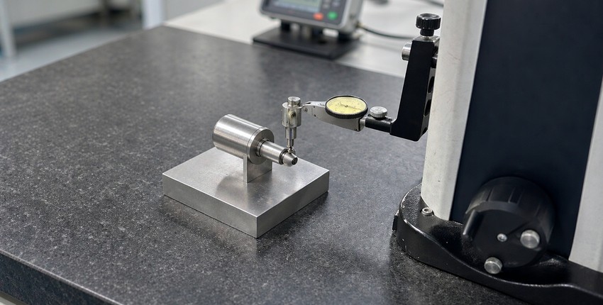
On our floor, position patterns go to the CMM first. The datum features are probed in the order stated in the frame, the alignment is built from those features, and each toleranced feature is reported with its true position value and the percentage of zone consumed. For patterns with MMC modifiers, the report lists the feature size beside the pass limit so the bonus tolerance is visible rather than buried.
Conventional tooling still has a place. A pin gauge made at the virtual condition, the MMC size minus the position zone, is a fast functional check for a bolt pattern on the shop floor. It passes parts a CMM would pass and rejects parts a CMM would reject, which makes it a good first-line screen between machining and final inspection. What it cannot do is produce a number, so it complements the CMM report rather than replacing it.
The deeper pattern across this series holds here too: the datum order in the frame is the assembly order, and the inspection is only as meaningful as the alignment behind it. A report produced against the wrong datums is not a lenient report or a strict one. It is a report about a different part.
The industry context for tight location callouts appears across our robotics work, where joint housings stack position and coaxiality callouts on the same datum system. The CMM fleet that verifies them is listed on the equipment page, and the ISO grades behind general tolerance callouts are cross-referenced on the tolerance and fit reference page.
Frequently Asked Questions
What is the true position formula in simple terms?
True position equals twice the square root of the sum of the squared X deviation and the squared Y deviation of the measured feature location from its basic location. The doubling converts a radius into a diameter so the result compares directly with the cylindrical zone in the feature control frame.
Why does a position callout on a hole usually have a diameter symbol?
Because the tolerance zone is a cylinder around the basic axis. The diameter symbol says the stated value applies in every direction around the axis, which is what a fastener needs. Without it, the zone is two parallel planes and only one direction of offset is bounded.
Is coaxiality the same as concentricity?
In the ASME standard the term was concentricity; ISO uses coaxiality for the same idea. Both describe a cylindrical zone around the datum axis that must contain the median points of the toleranced feature. The evaluation is based on derived median points over the full surface, which makes it stricter in intent than position at the same value and more expensive to verify.
Should I use runout or coaxiality on a bearing journal?
For a journal that rotates in service, runout is usually the better callout: it is cheap to verify on a bench, it matches the failure mode, and it bundles form, orientation and location into one functional number. Coaxiality is worth the extra inspection cost when the requirement is purely geometric alignment and the rotating behavior is verified another way.
How much bonus tolerance does MMC add?
Exactly the amount the feature departs from its maximum material condition. A hole specified 6.5 plus 0.1 minus 0 has MMC at 6.5 mm; a hole measured at 6.58 mm earns 0.08 mm of bonus, which is added to the position zone. The bonus can never exceed the size tolerance plus the stated geometric zone, and it applies only when the frame carries the MMC modifier.
Can KGL inspect and report position on multi-hole patterns?
Yes. Patterns are inspected on the CMM with datum alignment built in the stated order, and reports list true position values, feature sizes and zone consumption per hole. Functional gauging at virtual condition is available as a first-line screen. Send the drawing with the datum scheme and the MMC modifiers, and we will confirm the achievable values and the inspection plan at quotation.
This article is general engineering guidance, not a binding manufacturing guarantee. Tolerance feasibility, inspection methods and reporting formats are confirmed per part based on drawings, materials, quantities and process review. Request a formal quotation for part-specific terms. (c) 2026 KGL. All rights reserved.
Related Articles
More from the Inspection & Metrology series.
Have a project in mind?
Send drawings to kgl@kglmfc.com or request a quote. We respond within 24 hours.
Request a Quote