When Do CNC Buyers Need GD&T Instead of Plus/Minus Tolerances?
Plus/minus tolerances control the size of one feature. GD&T controls how features relate to each other. Where the line sits, which callouts earn their place on a typical CNC part, and how each choice shows up in the quote you receive.
Key Takeaways
- Plus/minus tolerances control the size of a single feature. GD&T controls the relationship between features. Most drawings need both, and the split is simple: sizes stay plus/minus, functional relationships get datums and geometric callouts.
- Chained boxed dimensions inherit the error of every dimension before them, so two suppliers can each pass every size on their reports and still ship parts that will not assemble. Datums fix the measurement origin so results repeat between batches and between suppliers.
- On a typical CNC part, GD&T belongs on hole patterns that bolt to a mating part, sealing faces, and rotating journals. Bore diameters, wall thicknesses and non-functional chamfers stay in general plus/minus tolerances.
- Adding an MMC modifier to a position callout lets the tolerance grow as the hole departs from its smallest size, which mirrors how the mating fastener behaves and gives the shop room to hold yield without giving up function.
- Tightening every dimension to force quality costs twice, once in the quote and once in the lead time. Releasing non-critical features to a general tolerance and spending the tight callouts on the features that locate, seal or carry load produces a cheaper part that assembles.
Plus/minus tolerances control the size of a single feature: a bore diameter, a plate thickness, an overall length. That is enough for most prototype work and for non-critical dimensions. GD&T earns its place when features must relate to each other: a hole pattern that has to line up with a mating housing, a sealing face that has to stay flat, a shaft journal that has to run true in a bearing. The practical rule for buyers: keep plus/minus for sizes, add GD&T for relationships, and settle both before you request a quote, not after the first inspection fails.
1. What plus/minus tolerances do well, and where they stop
Plus/minus is the fastest way to communicate size. A bore at Ø10 +0.015/+0.004 mm tells a machinist exactly what to check with a plug gauge or a bore mic. Any single, self-contained dimension works this way: lengths, depths, wall thicknesses, radii.
The system stops working the moment two features must agree with each other. Take a four-hole pattern, each hole dimensioned ±0.05 mm from the plate edges. Every hole sits inside its own window, yet nothing controls the spread between the holes, and nothing says the pattern must match the mating part measured from the same surfaces. Two suppliers can each pass every dimension on their inspection reports and still ship plates that will not assemble. The size tolerance is fine. The relationship between features is uncontrolled.
2. Why boxed dimensions cause trouble on assemblies
When a drawing chains dimensions edge to edge, the style often called boxed or coordinate dimensioning, every tolerance inherits the error of the one before it. A housing 200 mm long with five features dimensioned from the left edge at ±0.02 mm each can legally place the last hole 0.04 mm off its nominal position once the overall length drifts. The mating cover, dimensioned the same way from its own edge, drifts in its own direction. Assembly discovers the mismatch on the line, not on the inspection report.
GD&T solves this with datums. You pick the surfaces that matter for assembly, call them A, B and C, and the position tolerance of each hole references those datums directly. Every shop now measures from the same starting points, so results repeat between batches and between suppliers, and the tolerance zone becomes a cylinder around true position instead of a stack of square windows. For the full symbol-by-symbol treatment, see our guide to location tolerances, which covers position, coaxiality and symmetry in detail.
3. Which features deserve GD&T on a typical CNC part
| Feature on the drawing | Plus/minus alone | Better as a GD&T callout |
|---|---|---|
| Hole or bore diameter | Yes, size only | Not needed |
| Hole pattern bolted to a mating part | Ambiguous from-edge dims | Position to datums |
| Sealing or gasket face | Flatness hides inside size ± | Flatness callout |
| Shaft journal in a bearing | Size does not control wobble | Circular or total runout |
| Mounting face against a housing | Thickness ± only | Perpendicularity or flatness |
| Non-functional pockets, chamfers, engraving | Yes, general ± | Leave alone |
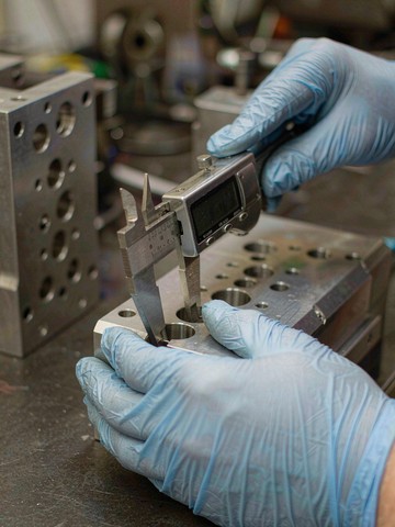
A short version of the table: GD&T belongs on functional interfaces, and almost everything else can stay in general plus/minus tolerances. One lever buyers underuse is the material condition modifier. Adding MMC to a position callout lets the tolerance grow as the hole departs from its smallest size, which mirrors how the mating fastener actually behaves. It keeps the assembly functional and gives the shop room to hold yield. Our feature control frame guide shows how the modifier reads inside the frame, and the complete tolerance guide explains how general tolerances and GD&T share one drawing. The fourteen characteristics themselves, from form through orientation to location, are covered in the series opener.
4. How GD&T changes the quote you receive
Shops price risk. A drawing where every dimension is ±0.02 mm forces the supplier to plan for the tightest value everywhere, whether or not the function needs it, and the quote climbs accordingly. The same part with general tolerances on non-critical features and GD&T on three functional interfaces is cheaper to make and easier to inspect.
Vague drawings cost money too. When datums are missing, each bidder invents its own, and you end up comparing quotes for three different parts. Expect clarification emails, or a risk margin quietly added to the price. Clear callouts let a shop map the process plan straight onto the drawing. At KGL we return quotes within 24 hours from complete 2D and 3D files, and when datums are already defined the machining plan follows them. A datum-bearing aluminum plate, for instance, goes on a Mazak VARIAXIS C-600 five-axis center so the mounting face and the hole pattern finish in one setup, which is how positional relationships hold without re-clamping error.
5. How to prepare a drawing before you send it for a quote
A five-minute pass over the drawing prevents most of this:
- Define datums from function: the surfaces that touch the mating part first.
- Apply position to hole patterns, flatness to sealing faces, runout to rotating surfaces.
- Release non-critical dimensions to a general tolerance and let the functional features carry the tight callouts.
- State the expected verification method when it matters, such as a CMM report or first article inspection.
- Send the STEP file together with the 2D so the shop can see the real geometry.
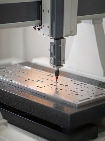
Then ask one question in your RFQ: how will these callouts be verified? A shop that answers with a CMM plan (at KGL, Hexagon GLOBALS bridge machines with 0.0015 mm accuracy and full first article reports) is telling you it reads GD&T for a living. A shop that answers with a vague promise to check everything has not planned anything yet. If you want the reference tables we work from, the engineering reference centre carries the tolerance and fit data behind these callouts, and the quote page lists what to attach so the first answer comes back complete.
6. From Our Shop Floor
Two revisions of the same aluminum bracket make this point better than any tolerance table can.
Revision A called out ±0.05 mm on six bolt holes and nothing else. Our Mazak VARIAXIS C-600 held every one of those dimensions, and the size reports came back clean. Then the parts reached assembly, where every housing needed bench hand-fitting: 38 minutes per part, and a 22% reject rate.
Revision B kept the same machine, the same tooling and the same material. What changed was the drawing language. We added a datum scheme A-B-C and put true position at ⌀0.08 mm on the hole pattern. The Zeiss CAPTUM CMM reported a maximum deviation of 0.041 mm, the first article cleared its fit-check immediately, cycle time fell from 38 minutes to 26 minutes, and bench rework went to zero.
The machine never changed. The drawing did.
Frequently Asked Questions
Do prototype drawings need GD&T too?
For a one-off bracket with no mating constraints, general plus/minus is fine. But if the prototype validates an assembly that will go to production, put the real GD&T on it. The prototype should pass or fail for the same reasons the production part will.
Is GD&T expensive to inspect?
Not on a CMM. Position, flatness and runout are direct measurements on Hexagon or Zeiss bridge machines, and our inspection floor runs them daily at 0.0015 mm machine accuracy. MMC modifiers can even loosen the effective tolerance as holes grow toward their largest size, which raises yield instead of cost.
What happens if I leave GD&T off a critical pattern?
The shop chooses its own datums and its own inspection origin. Parts pass individual dimensions, yet two batches may not interchange. We have received drawings where the mating cover was dimensioned to a different edge than the base part, and the first assembly attempt found the mismatch.
Can I just tighten everything to ±0.01 mm and skip GD&T?
You will pay for it twice, once in the quote and once in the lead time. Tight-everything drives extra finishing passes and scrap risk on features that never mattered. Our standard tolerance is ±0.005 mm, and ±0.002 mm is achievable on selected five-axis features verified by 100% CMM inspection. Spend that capability on the features that carry load, seal, or locate.
Where do I learn the symbols themselves?
This article covers when to use GD&T, not what each symbol means. For the symbols, see our guides to the 14 geometric characteristics and the feature control frame, plus the tolerance and fit reference page for ISO 286 tables.
This article is general engineering guidance, not a binding manufacturing guarantee. Tolerance feasibility, inspection methods and reporting formats are confirmed per part based on drawings, materials, quantities and process review. Request a formal quotation for part-specific terms. (c) 2026 KGL. All rights reserved.
Related Articles
More from the Inspection & Metrology series.
Have a project in mind?
Send drawings to kgl@kglmfc.com or request a quote. We respond within 24 hours.
Request a Quote