Mold and Die CNC Machining: Steel Choice, Staging and Hard Milling
Tool steel choice, staged roughing and hard milling against EDM for mold and die work, plus the acceptance checks before a cavity is signed off
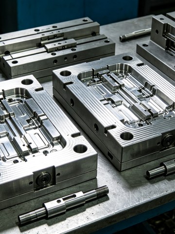
A mold cavity is the only machined part whose errors are manufactured a million times. A 0.02 mm step on a core becomes a witness line on every shot, and a polishing mark on a cavity face becomes a texture on every product the customer ships. That is why toolroom work carries tolerances that look excessive next to general machining, and why the sequence from rough block to polished surface matters more than any single operation in it.
This guide is written from the programming side: which steels arrive in which condition, how much material has to be left for heat treatment and polishing, how roughing and finishing are staged on hard material, when hard milling beats EDM, and what a tooling shop should check before a cavity is accepted. It assumes the reader is either buying tooling or building it, and cares about the third and fourth decimal place for a reason.
At a glance
- Cavity dimensions are cut to the shrink-adjusted size, and steel is removed on the safe side because a cavity that is 0.03 mm small can be corrected while one that is large cannot.
- Prehardened P20 and 718 are machined in one condition. H13, S136 and D2 are machined soft and hardened after, which means allowance, distortion and a second setup discipline.
- Hard milling at 50 HRC and above is a light cut, high speed process. The failure mode is tool deflection, not spindle power.
- EDM leaves a recast layer of a few micrometres that has to be removed where fatigue or polish matters.
1. Why Does Every Micron in the Cavity Multiply?
Injection molding works by shrinkage, so the cavity is never the nominal part size. A polypropylene part that measures 100 mm in the drawing needs a cavity around 98.4 mm at 1.6 percent shrinkage, and the exact value depends on grade, wall thickness, gate location, mold temperature and packing pressure. The toolmaker is therefore working to a number that is derived rather than given, and every small error in the shrink assumption lands on the part.
Two habits follow. First, the shrink figure is confirmed against the molder's own data and, where possible, against a trial shot from a single cavity before the full tool is cut. Second, the cavity is cut on the safe side: slightly under size on external features and slightly over on internal ones, with polishing stock left so the tool can be brought in by polishing rather than by welding. A cavity that is 0.03 mm undersize can be corrected in an afternoon. A cavity that is 0.03 mm oversize has to be welded, and a welded cavity face is never the same again.
The multiplication effect also changes how tolerances are distributed. If a part has a critical dimension of plus or minus 0.05 mm and the process contributes plus or minus 0.03 mm, the tool has about 0.02 mm of budget for everything: cavity machining, polish removal, plating thickness if there is any, and thermal movement during the run. Writing that budget down before cutting is the difference between a tool that is accepted first time and a tool that goes back to the bench three times. The same stack logic is set out in our tolerance guide.
2. Which Tool Steels, and What Do They Cost to Cut?
Steel selection is driven by three questions: how many shots, what the plastic or the die workload does to the surface, and whether corrosion from the melt or the coolant matters. The grades below cover most of the work we see, and the important column is the condition the steel arrives in, because that decides the entire process plan.
P20 at 1.2311 is the workhorse for medium volume tools. It arrives prehardened at 28 to 32 HRC, machines cleanly with coated carbide and does not need a heat treatment step, which keeps lead time short. 718 at 1.2738 is the same family with nickel added for through hardness on thicker sections, typically 30 to 34 HRC, and it is the choice where a P20 block would be soft in the middle.
H13 at 1.2344 and S136 at 1.2083 arrive annealed, around 235 HB, and are hardened after machining to roughly 48 to 52 HRC and 50 to 54 HRC respectively. That sequence is what makes them durable and what makes the process harder: cutting soft means leaving allowance, and hardening means accepting distortion that has to be corrected afterwards. S136 adds corrosion resistance for PVC, medical grades and anything with aggressive chemistry. D2 at 1.2379 goes harder still, 58 to 62 HRC, and is more often ground than milled after treatment.
| Grade | Delivery condition | In service hardness | Typical work | Machining note |
|---|---|---|---|---|
| P20 (1.2311) | Prehardened, 28 to 32 HRC | As delivered | Medium volume injection tools, housings | One condition, no heat treat step, plan for a final light pass |
| 718 (1.2738) | Prehardened, 30 to 34 HRC | As delivered | Thick sections, large cores | Harder skin at the surface, take a cleanup pass before measuring |
| H13 (1.2344) | Annealed, around 235 HB | 48 to 52 HRC | Die casting, high volume, hot work | Leave 0.3 to 0.5 mm per surface, harden, then finish by hard milling or grinding |
| S136 (1.2083) | Annealed, around 235 HB | 50 to 54 HRC | Corrosive plastics, medical, PVC | Same allowance as H13, keep it clean to avoid rust between operations |
| D2 (1.2379) | Annealed, around 240 HB | 58 to 62 HRC | Blanking and forming dies | Grind after hardening, hard milling only for light cleanup |
| 1.2316 | Prehardened, 30 to 34 HRC | As delivered | Corrosion resistant molds | Stainless behavior, keep the tool cutting to avoid work hardening |
3. How Should Roughing, Semi Finish and Finish Be Staged?
Staging exists for two reasons: to move material fast without loading the finishing tool, and to let the part settle between operations so the last cut is taken on a stable workpiece. On a 400 mm block, roughing removes the majority of the volume with a large radius or high feed cutter, leaving 0.5 mm on the surfaces that will be finished. Semi finish brings that to 0.12 to 0.15 mm, and finish takes the last 0.03 mm at a small stepover with a new tool.
The roughing strategy matters because it decides how much heat goes into the block. Trochoidal or constant engagement paths keep the cutter in a controlled arc of contact and let the tool run at higher feed without the temperature spikes that cause a deep pass to spring back. On a deep cavity the same idea applies to the side walls: a constant chip thickness avoids the moment when the cutter exits a corner and the load drops, which is where chatter starts.
Semi finish is where the accuracy actually gets established, and it is the stage that the axis count changes most. Finishing a wall that was left with an uneven allowance means the tool meets varying load, deflects by different amounts and leaves a wavy surface that polishing cannot remove without losing the form. Bringing the allowance to a uniform 0.12 mm removes that variation, and it also reveals the areas where the roughing tool could not reach, which are the areas that need a smaller cutter before the finishing tool goes in.
Tool length, runout and the limits of a finish pass
In a deep cavity the finishing tool is usually long and thin, and its deflection is the accuracy limit, not the machine. A 6 mm ball nose tool with 60 mm of stick out will bend measurably under normal finishing forces, and the deflection shows up as a wall that is straight at the top and tapered at the bottom. The practical controls, familiar from any surface finish review, are to keep the length to diameter ratio at four or below wherever the geometry allows, to use a shrink fit or hydraulic holder with runout under 5 micrometres, and to take a spring pass where the wall tolerance is tight.
Runout deserves its own line because it is invisible in the program and obvious in the surface. A tool with 20 micrometres of runout cuts with one flute taking most of the load, which halves tool life and leaves a periodic mark at the flute frequency. In a mirror polish cavity that mark is still visible after polishing, and the only fix is to cut it again.
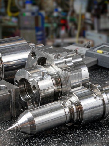
4. Hard Milling or EDM?
Both processes can hold a tolerance on hardened steel, and they fail in different ways. Hard milling removes material with a cutter, leaves a surface around Ra 0.4 micrometres with no recast layer, and can reach most geometry that a cutter can enter. EDM erodes with a wire or an electrode, reaches sharp internal corners and deep ribs that no cutter can, and leaves a recast layer of a few micrometres plus a heat affected zone underneath it.
That recast layer is the reason EDM is not automatically the finishing choice. On a mold surface that will be polished, the layer is removed by polishing, and there is no issue. On a die edge that will see impact, or a surface that will carry fatigue load, the layer has to be removed deliberately, and the removal changes the dimension. The rule we work to is straightforward: use hard milling wherever the geometry permits, and reserve EDM for corners, ribs, sharp edges and features a cutter cannot reach, then polish or stone the recast layer off those areas.
| Criterion | Hard milling (48 to 62 HRC) | EDM (sinker or wire) |
|---|---|---|
| Achievable tolerance | About 0.01 mm on a rigid setup | About 0.005 mm, better on small features |
| Surface finish | Ra 0.4 or better, no recast | Ra 0.1 to 0.2, with recast layer to remove |
| Sharp internal corners | Limited by cutter radius, typically 0.5 mm minimum | Any radius the electrode can form |
| Deep ribs and slots | Limited by tool length and deflection | Reaches where a cutter cannot, slower as depth grows |
| Setup and tooling | One setup, tools on the shelf | Electrode design and manufacture per feature |
| Where it loses | Thin walls, unsupported geometry, very sharp detail | Large areas, where time scales with surface area |
A worked comparison from our own scheduling makes the trade visible. On a twelve cavity tool with 0.8 mm corner radii, the hard milling route covers the cavity faces and the parting line in roughly 14 hours of spindle time, one setup, and leaves a surface that needs a short polish. The EDM route needs three electrodes per cavity shape, about 10 hours to make them, and 22 hours of burn time, plus a longer polish to remove recast. Both routes produce an acceptable tool. The difference is that one of them ties up a milling machine for a day and the other ties up an EDM for two and a half days plus electrode work, and which one is cheaper depends on what else is in the shop that week.
5. Where Does Five Axis Change the Answer?
Five axis work in a toolroom usually means 3 plus 2, using the two rotary axes to position rather than to move simultaneously. That is enough to machine angled sliders, lifters, side actions and deep cavities from a direction that keeps the tool short and rigid, and it removes the multiple setups that would otherwise introduce re indication error into features that must line up.
The second gain is datum continuity. A core and its cavity insert often have to be machined so that the shut off lands correctly, and doing both in one setup on one machine, from one datum, is far more reliable than machining them separately and hoping the fixtures agree. On a tool with a slide that has to travel in a pocket, the pocket and the slide are usually machined as a pair for the same reason.
The limits are practical. Five axis machines with a trunnion have less rigidity at the extremes of travel, so the finishing passes on a deep cavity are often better done at 3 plus 2 positions near the centre of the table than with the rotary axes swung out. And the post processor has to be verified, because a rotary move that is slightly wrong produces a gouge that no amount of polishing will fix.
6. How Is a Tool Accepted?
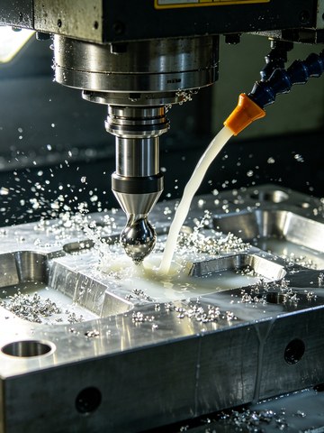
Acceptance is not a single measurement. A tool is accepted when the cavity dimensions are in tolerance, the shut offs close, the moving parts travel without binding, the cooling circuits hold pressure, the surface is at the specified texture, and a trial shot produces a part that meets the drawing. Each of those has a different method and each can fail independently.
| Check | Method | Typical criterion |
|---|---|---|
| Cavity and core dimensions | CMM with the shrink adjusted nominal, report per feature | Within 0.02 mm unless the drawing states tighter |
| Parting line and shut off | Blue check plus feeler, trial clamp | No light gap, no crushing of the steel edge |
| Slide and lifter travel | Assembly on the bench, travel measured against the pocket | Free travel with 0.02 to 0.05 mm clearance, no binding at the end of stroke |
| Cooling circuit | Pressure test with water or air | 6 bar held for 30 minutes, no drop |
| Surface texture | Visual comparator against the agreed SPI or texture plaque | Match to the sample, not to a description |
| First shot part | Trial on the molder's press, dimensional report on the part | Part within drawing, with the process window recorded |
7. What Should a Tooling Shop Ask Before Releasing Steel?
Five questions prevent most of the rework we see. What is the confirmed shrink value, and who measured it? Which surfaces must be polished, and to what texture, because that sets the polishing stock. Is there a heat treatment step, and who controls the allowance and the correction after treatment? Which features are machined as a pair, because those have to be in one setup. And what is the trial shot plan, because a tool that is accepted without a shot is only half accepted, and the same first article discipline applies to every insert.
We machine mold and die components on three and five axis mills, with CNC milling for the bulk of the work and five axis for angled features and datum continuity, and we quote hard milling and EDM as separate lines so the customer can see what each route costs. Where a tool needs a quick prototype cavity before steel is committed, the same geometry can be cut in aluminum on our prototyping route, which is far cheaper than discovering a design error in H13.
Send the drawing, the steel grade and the trial shot requirement, and a quote is back within 24 hours with the process sequence stated. If the geometry would be cheaper with a different split between inserts and a solid cavity, the quote says so, on the same logic we apply in design for machining reviews.
Frequently Asked Questions
What tolerance do you hold on a mold cavity?
Plus or minus 0.005 mm is our standard machining tolerance, and on cavity work the practical target is usually plus or minus 0.02 mm against the shrink adjusted nominal, because polishing and heat treatment move the surface afterwards. Tighter is possible on specific features when the drawing asks for it.
Do you machine hardened steel above 50 HRC?
Yes, by hard milling with coated carbide and by grinding where the geometry suits. Above about 55 HRC the cut becomes very light and the tool length has to be kept short, so deep thin features may still go to EDM.
How much material should be left for heat treatment?
Typically 0.3 to 0.5 mm per surface for H13 and S136, with the exact figure depending on section size and the hardening route. Bores that must finish after hardening need the allowance stated on the drawing so it is not discovered at the machine.
Can you polish to a mirror finish?
We machine to the finish that polishing can start from, and polishing is either done in house or by a specialist partner depending on the texture required. The important part is leaving enough stock so the polishing removes the machining marks without changing the form.
Do you make the electrodes as well as the cavity?
Yes. Electrodes are machined from copper or graphite to the same datum as the cavity, and the burn is set up against that datum so the feature lands where the model says it does.
How fast can you quote a tooling component?
Within 24 hours for a complete drawing set including steel grade and heat treatment requirement. Tools with several inserts and sliders sometimes need one exchange about the split, because that decision changes both the machining hours and the risk.
This article is general engineering guidance, not a binding offer. Tolerances, cost and lead time depend on part geometry, material, quantity and the drawing package you release. Request a quotation for part specific terms. (c) 2026 KGL Machining & Electronics, Shenzhen.
Related Articles
More from the CNC Milling series.
Have a project in mind?
Send drawings to kgl@kglmfc.com or request a quote. We respond within 24 hours.
Request a Quote