CNC Machining Tolerances: A Complete Guide to Standard, Precision, and High-Precision Tolerances
What tolerances CNC processes actually hold, what drives cost, and how to specify them: ISO 2768 bands, material effects, and KGL's ±0.005 mm standard with ±0.002 mm on critical 5-axis features.
Key Takeaways
- KGL standard tolerance is +/-0.005 mm; +/-0.002 mm is held on specific features with 100% CMM verification.
- ISO 2768-m covers general dimensions; drawing-specified tolerances always take precedence.
- Material matters: aluminum, stainless, titanium and engineering plastics each behave differently under the same tolerance callout.
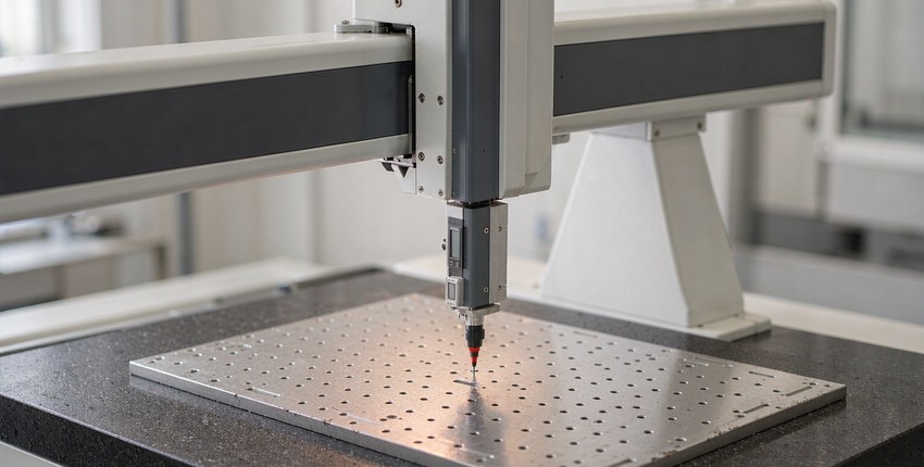
- Every tolerance report traces back to Zeiss and Hexagon CMM measurement uncertainty statements.
A tolerance tightened from ±0.05mm to ±0.01mm can increase machining cost by 300% while adding zero functional value if the dimension is non-critical. At KGL, our DFM engineers identify which dimensions genuinely require tight tolerances and which can be relaxed. With 13 years of precision machining experience, Mazak 5-axis and turn-mill equipment, and Zeiss and Hexagon CMM verification at 0.0015 mm class uncertainty, we deliver consistent tolerances across every monthly production run. This guide explains what tolerances are achievable, what factors affect them, and how to specify them correctly.
1. What Are Tolerances in CNC Machining?
A tolerance is the total allowable variation of a physical dimension from its nominal value, defined by upper and lower deviations. For example, a dimension of 10 ±0.05mm means the part may measure anywhere between 9.95mm and 10.05mm. Tolerances determine how parts fit and function in an assembly, whether they remain interchangeable across batches, and how they are inspected before delivery.
In practice, every manufacturing process has natural variation, and the tolerance you specify defines the acceptable window around the design intent. General tolerances are defined per ISO 2768-1 (metric) and ASME Y14.5 (geometric dimensioning and tolerancing). KGL's full band tables are published on the tolerance standards page.
2. Standard Tolerances by CNC Process
Tolerance capability varies by process, feature type, material, and part size. The table below summarizes standard and precision tolerance ranges that professional machine shops routinely hold in production:
| Process | Standard Tolerance | Precision Tolerance | High-Precision | Feature |
|---|---|---|---|---|
| CNC Milling (3-axis) | ±0.05mm | ±0.025mm | ±0.01mm | Linear dims |
| CNC Turning | ±0.05mm | ±0.013mm | ±0.005mm | Diameter |
| 5-Axis CNC Milling | ±0.025mm | ±0.01mm | ±0.005mm | Multi-axis features |
| Turn-Mill (INTEGREX) | ±0.005mm | ±0.005mm | ±0.002mm (full CMM check) | Complex geometries |
| Swiss CNC | ±0.025mm | ±0.013mm | ±0.005mm | Small diameter |
| Wire EDM | ±0.025mm | ±0.01mm | ±0.005mm | Profile cut |
| Surface Finish (standard) | Ra 1.6 | Ra 0.8 | Ra 0.4 | Surface roughness |
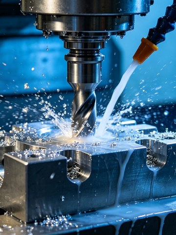
KGL's Mazak INTEGREX turn-mill centers hold ±0.005 mm as the shop standard and ±0.002 mm on critical features with full CMM verification, and Mazak VARIAXIS C-600 5-axis centers maintain ±0.005 mm on multi-axis features. These capabilities are verified through Zeiss and Hexagon CMMs with 0.0015 mm class measurement uncertainty.
3. Factors That Affect Achievable Tolerances
3.1 Material Properties
Aluminum alloys such as 6061 machine cleanly and hold tight tolerances well. Stainless steel and titanium work-harden, deflect under cutting forces, and generate more heat, making tight tolerances more demanding. Thermal expansion and residual stress also influence final dimensions. For example, aluminum 6061 expands 23.6 um/m-C versus titanium's 8.6 um/m-C.
| Material | CTE (um/m-C) | Machinability | Thermal Drift Risk |
|---|---|---|---|
| Aluminum 6061-T6 | 23.6 | Excellent (190%) | High |
| Stainless 304 | 16.0 | Moderate (45%) | Medium |
| Stainless 316L | 15.9 | Moderate (45%) | Medium |
| Titanium Ti-6Al-4V | 8.6 | Difficult (22%) | Low |
| Carbon Steel 45# | 11.6 | Good (65%) | Low |
| POM (Acetal) | 85.0 | Excellent | Very High |
3.2 Part Geometry and Feature Size
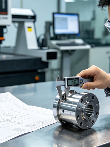
Large flat surfaces, thin walls, deep cavities, and very small features are harder to hold precisely. A long thin wall may flex during cutting, and a deep pocket limits tool reach and rigidity, both of which widen the achievable tolerance window. Walls below 0.5mm thickness for metals and 1.0mm for plastics require special fixturing strategies.
3.3 Machine Capability and Thermal Effects
Machine rigidity, spindle accuracy, tool wear, and workholding stability set the practical floor for achievable tolerance. KGL's temperature-controlled workshop and inspection room (20 +/- 1 C) eliminate thermal expansion variability between cutting and measurement. High-pressure through-spindle coolant on Mazak equipment manages cutting heat during precision operations.
4. How KGL Delivers Consistent Tolerances
4.1 DFM Review and Tolerance Rationalization
During DFM review, KGL engineers identify which dimensions genuinely require tight tolerances and which can be relaxed to save cost and lead time, without compromising function. This upfront analysis prevents both over-engineering and assembly failures. DFM feedback is provided within 24 hours of receiving drawings.
4.2 Equipment and Process Control
| KGL Equipment | Tolerance Capability | Application | Reference |
|---|---|---|---|
| Mazak VARIAXIS C-600 (5-axis) | ±0.005mm | Complex aerospace/medical | AS9100D |
| Mazak VARIAXIS J-500 (5-axis) | ±0.005mm | Multi-axis precision parts | ISO 9001 |
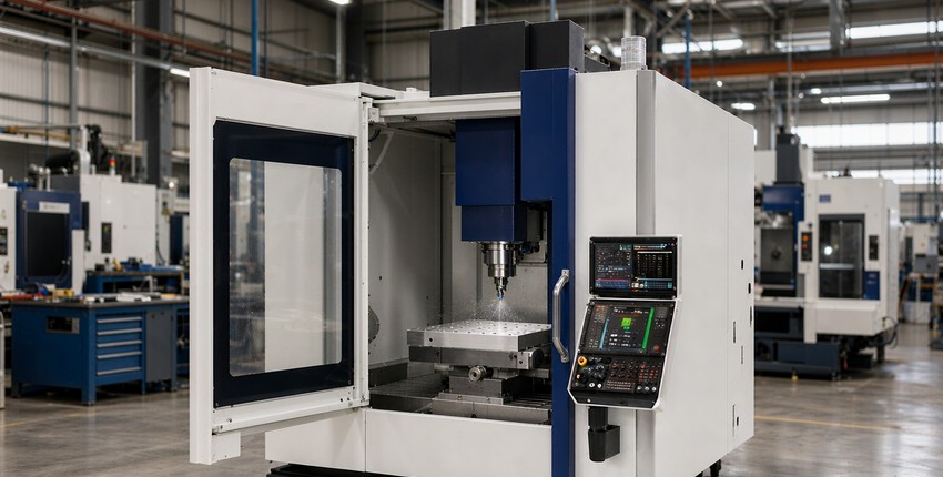
| Mazak INTEGREX i-250H / i-250HS (turn-mill) | ±0.005mm (±0.002mm with full CMM check) | Turn-mill compound | AS9100D |
| FANUC ROBODRILL machining centers | ±0.005mm | High-speed milling | ISO 9001 |
| Mazak-led CNC turning centers (20 units) | ±0.005mm | Precision turning, incl. mill-turn | ISO 13485 |
The full machine list, with quantities and process groups, is published on the equipment page and verified against the Fact Sheet each August.
4.3 Full Metrology and Quality Assurance
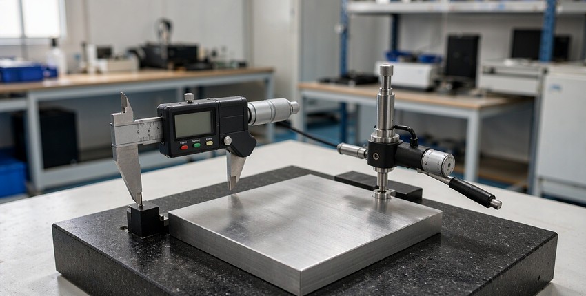
Critical dimensions and geometric tolerances are 100% verified using Zeiss and Hexagon CMMs (0.0015 mm class uncertainty). KGL holds ISO 9001:2015, ISO 13485:2016 (Medical Devices), and AS9100D (Aerospace) certifications, providing complete inspection reports with every batch. Sampling plans follow our AQL 2.5 acceptance sampling procedure. See also how thread quality depends on the same discipline: preventing thread galling in stainless steel.
4.4 Rapid Prototyping and Fast Iteration
KGL's 24-hour technical response and expedited prototyping policy allows you to validate critical tolerances and fit on real machined parts before committing to mass production, reducing iteration cycles and project risk.
5. Actionable Checklist for Specifying Tolerances
- Use ISO 2768-m (medium) or GB/T 1804-m as your default general tolerance; tighten only functionally critical dimensions.
- Match tolerance to process capability: ±0.005 mm as the shop standard across milling and turning, ±0.002 mm on critical 5-axis features with full CMM verification.
- Account for material thermal expansion in your tolerance calculation, especially for aluminum (CTE 23.6 um/m-C) and plastics.
- Specify geometric tolerances (GD&T per ASME Y14.5) instead of plus/minus tolerances for critical fits to avoid ambiguity.
- Request DFM review before production. A 0.05mm tolerance relaxation on a non-critical dimension can reduce cost by 30-50%.
- Share your critical dimensions early for DFM review. KGL provides free feedback within 24 hours through the quote form.
6. FAQ
What is the tightest tolerance KGL can achieve?
±0.002 mm on critical turn-mill and 5-axis features, verified with a full CMM layout. The shop standard is ±0.005 mm. All critical dimensions are verified 100% on Zeiss and Hexagon CMMs at 0.0015 mm class uncertainty.
What general tolerance standard should I reference on my drawing?
ISO 2768-m (medium) for general metric drawings, or GB/T 1804-m for Chinese standard drawings. Tighten only dimensions that functionally require it.
How does material choice affect achievable tolerance?
Aluminum 6061 holds tight tolerances well due to excellent machinability. Stainless steel work-hardens and generates more heat. Titanium deflects and wears tools faster. Plastics like POM have high CTE (85 um/m-C), requiring temperature-controlled machining.
Do you provide inspection reports with every batch?
Yes. Every batch ships with dimensional inspection reports verified on Zeiss and Hexagon CMMs. Critical dimensions receive 100% inspection; non-critical features are sampled per AQL 2.5.
What is your DFM feedback turnaround time?
24 hours from receipt of complete 2D drawings (PDF, DWG, DXF) or 3D models (STEP, IGES, SolidWorks). DFM review is free of charge.
Can you machine to aerospace tolerances?
Yes. KGL holds AS9100D certification for aerospace components. Typical aerospace tolerances of ±0.01mm on 5-axis features and ±0.005mm on turn-mill features are routinely achieved.
For the standards behind these numbers, see our tolerance standards reference, or send your drawing through the RFQ page for a DFM review.
Related Articles
More from the Inspection & Metrology series.
Have a project in mind?
Send drawings to kgl@kglmfc.com or request a quote. We respond within 24 hours.
Request a Quote