Surgical Robot Parts: Precision Machining Under ISO 13485
How surgical robot components are machined under ISO 13485: the parts that matter, material choices, the tolerances that decide motion accuracy, and the documentation package that travels with the lot.
Key Takeaways
- Surgical robot parts are judged on motion accuracy, cleanability and documentation, not on part count: one instrument arm link out of tolerance shows up as tracking error in the assembled system.
- 17-4 PH and 316L stainless dominate instrument-side parts, Ti-6Al-4V ELI covers structural components, and PEEK handles electrically insulating and radiolucent parts.
- ±0.005 mm is KGL's standard commitment across milling, turning and five-axis work; ±0.002 mm applies to selected five-axis features with 100 percent CMM verification.
- The paperwork travels with the lot: material certificate, lot traceability, dimensional report, first article inspection and a certificate of conformity.
Surgical robot parts live in a narrow band of work. They are small enough to be held in one hand, tight enough that a few microns decide whether an instrument arm tracks straight, and documented well enough to survive an audit. This guide covers what changes when a part is going into a surgical robotics program rather than a general medical device, and which process decisions decide the outcome.
KGL is an ISO 13485 certified machine shop in Shenzhen with 100+ CNC machines, including 11 five-axis centers. We machine instrument and equipment components for medical and surgical robotics programs: arm links, actuator and joint housings, end effector brackets, trocar and cannula guides, and camera or sensor housings. We do not manufacture implantable devices, and nothing described here is intended for implantation.
1. What separates a surgical robot part from other medical work
Four requirements stack on top of each other, and each one constrains the process.
Motion accuracy. A surgical instrument arm is a kinematic chain. Every link, pivot and mounting face adds its own error, and the assembled arm tilts the instrument tip somewhere you did not plan. A housing whose bearing bore runs 8 microns eccentric, or whose mounting face is not square to the bore axis, becomes visible tracking error at the distal end of the chain.
Cleanability. Parts sit near the sterile field. Any pocket, blind thread or unfinished surface that traps residue becomes a reprocessing problem, so surface roughness and edge condition are functional requirements, not cosmetic ones. Sharp burrs on a cannula guide get rejected; so do surfaces that hold onto cleaning agent.
Repeat cycle durability. Instruments and their carriers are reprocessed between procedures. Steam autoclave at 134 degrees Celsius, hydrogen peroxide plasma, and gamma sterilisation each stress a material differently, and a finish that passes one cycle may not survive two hundred.
Documentation. Under ISO 13485 the machined component has to be traceable back to its material lot and forward to the device lot. A shop that ships good parts with weak paperwork creates an audit finding for the device manufacturer, which is why the document package matters as much as the geometry.
2. The parts that actually get machined
Surgical robotics programs buy mechanical components in a recognisable pattern. The table below is the shape of a typical bill of materials.
| Component | Typical material | Feature that decides acceptance |
|---|---|---|
| Instrument arm link | 7075-T651 aluminium, Ti-6Al-4V ELI | Bore-to-face squareness, mass budget |
| Actuator and joint housing | 17-4 PH stainless, 6061-T6 | Bearing bore concentricity, gear pocket position |
| End effector bracket | 316L stainless, 17-4 PH | Mounting hole pattern position, edge condition |
| Trocar and cannula guide | 316L stainless | Bore roundness, internal surface finish, burr-free entry |
| Camera and sensor housing | 6061-T6, PEEK | Optical axis alignment, wall thickness |
| Instrument shaft | 17-4 PH, 304 stainless | Straightness, wall thickness, runout |
| Sterile barrier and carrier fixture | PEEK, PPSU, 316L | Flatness, thermal stability |
3. Material selection that survives sterilisation
Material choice is driven as much by the reprocessing cycle as by strength. Typical published property values are listed below and are intended as orientation, not as a substitute for the material certificate that comes with the lot.
| Material | Why it is specified | What to watch |
|---|---|---|
| 316L stainless | Corrosion resistance, common in contact-adjacent instrument parts | Gummy chip, work hardening; needs disciplined feeds |
| 17-4 PH stainless | High strength plus corrosion resistance after H900 or H1025 aging | Heat treat condition changes machinability and final size |
| Ti-6Al-4V ELI | Strength-to-weight ratio, biocompatibility track record | Low thermal conductivity, tool wear, springback on thin walls |
| 7075-T651 aluminium | Stiffness per gram on arm links | Not the grade for repeated caustic cleaning without coating |
| 6061-T6 aluminium | Housings, brackets, camera bodies | Anodising adds a per-side dimensional change |
| PEEK | Electrically insulating, radiolucent, autoclave stable | Residual stress moves thin sections after machining |
| PPSU | Transparent, repeated steam sterilisation | Clamping marks, stress crazing |
Two rules save both time and money. First, decide the sterilisation route before the grade is fixed, because a material that hydrolyses under steam is the wrong answer no matter how well it machines. Second, if a part needs both a stainless surface and an aluminium body, split it into two components rather than asking one alloy to do both jobs.
4. Tolerances: where the tight band belongs
The mistake that shows up in quotations is a drawing with tight tolerances everywhere. Precision costs cycle time and first-pass yield, so the tight band should sit on the features that carry the function.
Our standard commitment is ±0.005 mm across milling, turning and five-axis work. Selected five-axis features can be held to ±0.002 mm with 100 percent CMM verification. Beyond that, per-feature calls such as a 0.005 mm roundness on a bearing seat or a 0.01 mm flatness on a sealing face are quoted individually because they change the process route, not just the inspection plan.
A practical tolerance map for a surgical robot part looks like this.
| Feature | Band that matters | Why |
|---|---|---|
| Bearing bore diameter | ±0.005 mm, roundness 0.005 mm | Sets radial play in the joint |
| Bore-to-face squareness | 0.01 mm over the face | Sets angular error that accumulates along the chain |
| Mounting hole pattern | Position 0.02 mm on the datum system | Decides whether two subassemblies bolt together without shimming |
| Sealing face | Flatness 0.01 mm, Ra 0.4 to 0.8 µm | Seal seating and residue release |
| Free surfaces, non-mating | ±0.1 mm | No functional load; leave it loose and keep cost down |
Datum strategy deserves a deliberate decision. A single primary datum carried through turning, five-axis and inspection removes most of the argument at first article. Where the part is too flimsy for direct clamping, we machine soft jaws or a dedicated fixture for the second operation so the location repeats run to run.
5. Surface finish and cleanability
Finish is a functional callout on these parts. For instrument-side components the working range runs from Ra 0.4 µm on sealing and sliding surfaces to Ra 1.6 µm on general machined faces, with the practical floor set by the geometry rather than the machine: a deep pocket with a small corner radius reaches a different finish than an external diameter.
| Finish | Where it is used | Dimensional effect |
|---|---|---|
| As-machined, Ra 1.6 to 3.2 µm | Internal brackets, non-contact surfaces | None beyond the machining tolerance |
| Fine finish pass, Ra 0.4 to 0.8 µm | Sealing faces, slider contact, cannula bores | None, achieved in the cut |
| Passivation, ASTM A967 | Any free-machining or 17-4 PH stainless part | None measurable; removes free iron |
| Electropolishing | Instrument shafts and cannula surfaces | Removes 5 to 25 µm per surface; dims must be quoted with allowance |
| Anodising, Type II or III | Non-contact aluminium housings and brackets | Adds per-side thickness, so mask or pre-size tight features |
| Bead blasting | Matte finish on aluminium and stainless | Edge break only; not for sealing faces |
Two finishing decisions cause most of the rework on medical programs. Electropolishing removes material, so a bore called at final size and then polished will come back oversize unless the drawing states the allowance. Anodising builds thickness on every exposed surface, so a masked-thread note or a pre-machine allowance has to appear on the drawing rather than in a phone call after the parts are made.
6. The machining route
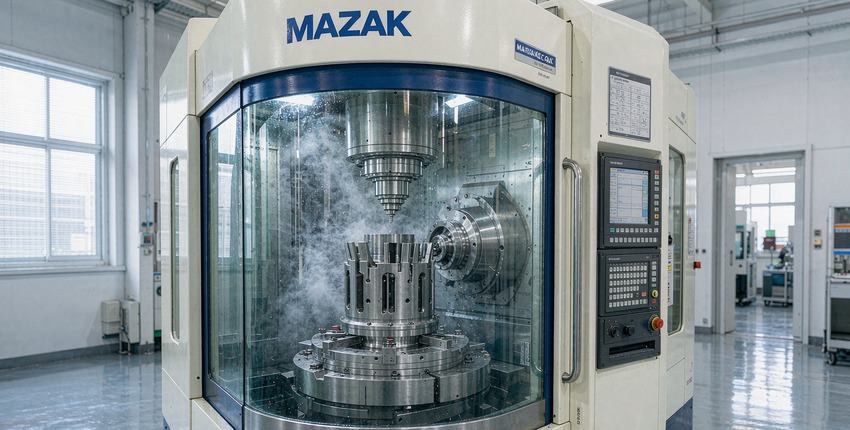
Small complex parts with several faces and tight relationships between them route onto five-axis work. Holding multiple faces in one setup removes the re-clamping error that otherwise appears between operations.
| Feature | Machine class | Reason |
|---|---|---|
| Joint housing with multiple bored faces | Five-axis machining center | One setup, one datum, no re-clamp stack-up |
| Instrument shaft, long and small diameter | CNC turning, then mill-turn for flats | Turning holds roundness and straightness; mill-turn avoids a second locating operation |
| Thin wall cup or cover | Five-axis with high-speed light cuts | Low radial force limits deflection and ovality |
| PEEK insulator | 3-axis or five-axis, sharp tooling | Sharp edges and low clamping pressure avoid stress marks |
Three process controls separate a part that passes twice from a part that passes every time.
- Rough, stress relieve, finish. On thin walls and large pockets, roughing removes most of the stock and lets the part move before the finishing pass. Natural aging or a controlled low temperature cycle closes that window.
- Thermal stability before final cuts. A 24 hour soak at controlled room temperature before finish machining removes the drift that comes from a part that is still warm from the previous operation.
- Cutting temperature control. High pressure coolant through the holder keeps heat out of a small part, which matters most on titanium and on pockets with limited access.
7. Inspection and the report that goes with the lot
Inspection on a surgical robot part is not a final gate, it is a programme. First article confirms the process, in-process checks confirm it has not drifted, and final inspection confirms what actually shipped. Our inspection room carries 40+ instruments, including Zeiss CAPTUM CMMs with a stated accuracy of ±0.0005 mm, vision systems and dedicated roundness checking.
| Document | What it proves |
|---|---|
| Material certificate, EN 10204 3.1 | Grade and heat number of the stock that went into the part |
| Lot traceability record | Links the machined lot to the incoming material and to the operations performed |
| First article inspection report | Every dimension on the drawing, measured against the nominal and the band |
| Dimensional report per lot | Critical characteristics measured on the parts that shipped |
| Surface finish and hardness records | Ra values, and hardness after aging on 17-4 PH work |
| Certificate of conformity | Statement that the lot was produced to the drawing and the purchase order |
| Process and inspection records | What ISO 13485 auditors ask for when the device maker is audited |
For CMM work on complex geometry we build the inspection program from the same 3D model that drove the toolpaths, and we align to the drawing datum system rather than to a convenient face. If your quality team wants the raw CMM points rather than a pass or fail sheet, ask for them at the quotation stage so the report format is agreed before the first part is cut.
8. Quoting a surgical robot part
A quote that holds up needs five things: a 2D drawing with the tolerance block and finish callouts, a 3D model in STEP or IGES, the quantity split between samples and production, the sterilisation route, and the documentation the order has to carry. Add the critical feature list if tolerances stack through an assembly, and say whether the part is a new design or a transfer from another shop. A transfer part usually needs a first article on our process regardless of how well it ran before.
Standard practice at KGL is a quotation within 24 hours from a complete package and expedited first articles on a scheduled window for parts that route onto our five-axis and mill-turn cells. There is no minimum order quantity. Parts that need outside finishing or special stock carry a longer lead time, and the quote states the routing behind the date so you can see where the time goes. Send the drawing and model through the RFQ page and the review starts the same working day.
Frequently Asked Questions
Does KGL manufacture implantable devices?
No. We machine instrument and equipment components for medical and surgical robotics programs as a contract supplier under ISO 13485. Implantable devices carry additional regulatory obligations that sit with the device manufacturer, and we state this plainly rather than blurring the line.
Which materials do you recommend for surgical robot arm links?
7075-T651 aluminium when stiffness per gram decides the design and the part is coated or kept out of repeated caustic cleaning, and Ti-6Al-4V ELI where strength and corrosion resistance both matter. Stainless is usually too heavy for a moving link unless the part is small.
Can you hold ±0.002 mm on a surgical robot component?
On selected five-axis features, yes, with 100 percent CMM verification and a stated inspection method. It is quoted feature by feature rather than as a blanket promise, because the process route and the cost both change when the band tightens that far.
How do you handle cleanability requirements?
By treating edges and internal surfaces as functional callouts. We break sharp edges, control Ra on bores and sealing faces, avoid blind pockets where the design allows, and inspect the features that decide whether the part releases cleaning residue.
What documentation ships with a surgical robot part order?
Material certificate, lot traceability, first article inspection report, dimensional report on critical characteristics, surface finish and hardness records, and a certificate of conformity. We can add raw CMM point data or a custom report format if it is agreed at quotation.
Can you take over a part that another shop already qualified?
Yes, and it needs a first article on our process. Fixtures, datum strategy and machine dynamics all differ, so a transferred part is treated as a new program until it has proven repeatable in our shop. Send the drawing, the model and the last inspection report and we will quote the transfer with the first article included.
Do you sign NDAs before drawings are shared?
Yes, and we recommend it for anything with proprietary geometry. Send the NDA first and the drawings second. Our D-U-N-S number, 54-443-4542, ties the signature to a verifiable legal entity, and you can check our ISO 13485 scope and the quality system behind it.
This article is general engineering guidance, not a binding manufacturing guarantee, and it does not constitute regulatory advice on device classification or submission. Tolerances, lead times and pricing are confirmed per part based on drawings, materials, quantities and process review. Request a formal quotation for part-specific terms. (c) 2026 KGL. All rights reserved.
Related Articles
More from the Medical series.
Have a project in mind?
Send drawings to kgl@kglmfc.com or request a quote. We respond within 24 hours.
Request a Quote