Form Tolerances Explained: Straightness, Flatness, Circularity, Cylindricity
The four form tolerances in plain language: what each one controls, the shape of its tolerance zone, how each is measured, and a real case where a roundness failure turned out to be a stress problem, not a machine problem.
Key Takeaways
- Form tolerances control shape with no datum. Straightness, flatness, circularity and cylindricity describe a feature against its own perfect geometry, not against another feature.
- The tolerance zone shape tells you what the inspector will measure: two lines, two planes, two concentric circles, or two coaxial cylinders.
- Flatness and parallelism are not the same thing. Flatness needs no datum and can be verified on a surface plate; parallelism needs a datum and means nothing without one.
- A roundness failure on a thin-wall part is more often a stress relief problem than a machine problem. Check the process route before blaming the spindle.
- Cylindricity is the most expensive of the four to verify because it needs full surface scanning, so reserve it for bearing seats and sealing surfaces where the function justifies the cost.
Form tolerances are the foundation of GD&T, and they are also the group buyers misread most often. The reason is simple: they look like size callouts. A note that says "flat within 0.01" feels like the plus/minus tolerances next to it, but it answers a different question. Size tolerances control how big a feature is. Form tolerances control how true its shape is, and they do it without reference to any other feature.
This article covers the four form characteristics from the GD&T basics overview: straightness, flatness, circularity and cylindricity. For each one you get the definition, the tolerance zone shape, where it earns its place on a drawing, and how a shop actually verifies it. The article closes with a real case where a tight roundness callout failed for a reason that had nothing to do with the machine.
1. What makes a tolerance a form tolerance
The defining property of the form group is the absence of a datum. A feature control frame for flatness contains only two things: the flatness symbol and a number. There is no datum letter, because the surface is being compared to its own ideal self, not to another surface.
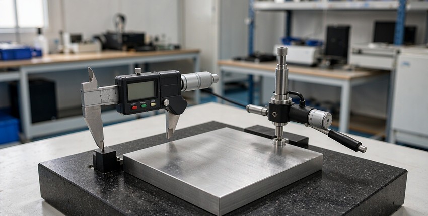
This has a practical consequence for inspection. Form can be checked on the feature alone. A surface plate, a dial indicator and a competent inspector can evaluate most form callouts without a CMM. Orientation and location callouts cannot be evaluated that way, because they need the datum features physically present and referenced.
| Characteristic | Tolerance zone | Typical application |
|---|---|---|
| Straightness | Two parallel lines, or a cylinder if applied to an axis | Long shafts, rails, guide edges |
| Flatness | Two parallel planes | Sealing faces, mounting faces, fixture bases |
| Circularity | Two concentric circles in one cross-section | Bearing seats, rotating seals, lens seats |
| Cylindricity | Two coaxial cylinders over the full surface | Hydraulic bores, spindle journals, precision pins |
2. Straightness
Straightness limits how much a line element may bend. Applied to a surface, it controls individual line traces across that surface. Applied to a cylindrical feature's axis, written with a diameter symbol, it controls the entire centerline inside a cylindrical tolerance zone.
The axis version is the one that matters on shafts. A long shaft can be within diameter tolerance everywhere and still be banana shaped; the size limits say nothing about the centerline. Axis straightness is what keeps the shaft from whipping in a bearing or binding in a linear guide.
Verification on the shop floor is a surface plate and a height gauge with a dial indicator, tracing a series of lines along the feature and recording the deviation. On a CMM it is a scan of the axis with a least-squares or minimum-zone evaluation. For long thin parts, straightness is often decided as much by workholding as by cutting: a shaft clamped hard at two points will spring when released, so the inspection result reflects the setup, not just the cutting.
3. Flatness
Flatness controls how much a surface deviates from a perfect plane. The tolerance zone is two parallel planes separated by the stated value, and every point on the surface must fall between them. No datum is involved, so the surface is evaluated in whatever orientation minimizes the deviation, which is exactly what a surface plate does naturally when the part is placed on it.
Flatness earns its keep on sealing faces and mounting interfaces. A pump cover that seals against a gasket, a fixture base that clamps onto a machine table, a flange face that bolts to a housing: each of these needs the whole face to contact, not three high spots. A common callout on a sealing face is flatness of 0.01 mm for a face under 100 mm across, tightening as the face grows or the pressure rises.
One inspection note worth knowing: a large thin face can measure flat when supported one way and wavy when supported another. Good practice is to state the inspection condition on the drawing, or to accept the free-state condition and let the part sit unconstrained on the plate. For thin parts that will be bolted down, a flatness callout measured in the constrained state is a legitimate and often wiser choice, but it must be said so explicitly.
4. Circularity
Circularity, usually called roundness, limits how much one cross-section may deviate from a perfect circle. The tolerance zone is two concentric circles whose radii differ by the tolerance value. Each cross-section is evaluated independently, which is why a part can pass roundness on every measured slice and still be a terrible cylinder: the slices may wander along the axis. Controlling that wander is the job of cylindricity.
Roundness matters where rotation is involved. A bearing seat with 0.005 mm roundness lets the race spin smoothly; the same seat with 0.03 mm roundness will transmit a once-per-revolution disturbance into whatever it supports. On optical and precision instrument parts, roundness on lens seats and bearing journals is frequently the tightest callout on the drawing.
Roundness is measured on a dedicated roundness tester, which rotates the part or the probe and plots the profile, or on a CMM with enough sampled points per cross-section. A bench fallback, a V-block and a dial indicator, gives a reading that mixes roundness with lobing effects and is only an approximation. It is useful as a quick screen, not as an acceptance method for tight callouts.
5. Cylindricity
Cylindricity is the comprehensive form control for round features. The tolerance zone is two coaxial cylinders separated radially by the tolerance value, and the entire surface must fall between them. One cylindricity callout simultaneously bounds roundness at every cross-section, straightness of the axis, and taper along the length.
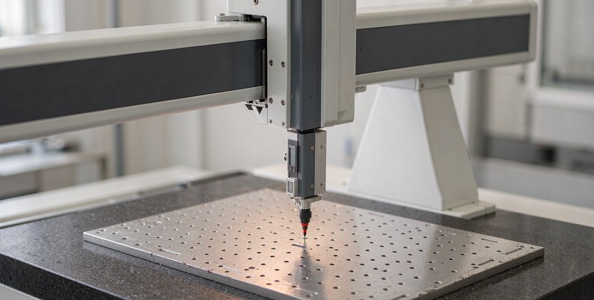
Because it is comprehensive, it is also expensive to verify. A proper evaluation scans the full surface, not a few slices, and the software minimizes the zone mathematically. That is why cylindricity belongs on features whose function justifies the cost: hydraulic cylinder bores, spindle journals, long precision pins, and sealing lands where leakage paths along the axis matter. On a feature where only the local fit matters, roundness plus a size tolerance is usually the more economical specification.
A practical purchasing note: when a drawing carries both cylindricity and a stack of separate roundness and straightness callouts on the same feature, the cylindricity value usually governs. Ask which one the supplier will inspect, and remove the redundancy, or you will pay for both.
6. Case: a thin-wall optical housing that failed roundness for a process reason
A multi-cavity housing for professional optical equipment shows how the four form tolerances interact on a real part, and how a failure that looks like a machining problem can be a planning problem.
The part is machined from a solid AL6061-T6 block, roughly pocketed on the inside, with intersecting cavities, seal grooves and bearing bores. The drawing required roundness and cylindricity within 0.005 mm on the bearing seats and lens-interface arcs, flatness of 0.01 mm on the sealing face, and a position of 0.008 mm on the bolt pattern, with surface roughness of Ra 0.8 µm. Everything was verified on a Zeiss CMM plus a dedicated roundness tester, with a full dimensional report per part.
The first trial run did not pass. Roughing removed roughly 80 percent of the material, and that broke the stock's internal stress balance. The remaining walls relaxed by microns after finish machining, and the relaxation showed up exactly where the drawing was strictest: circularity and flatness moved out of tolerance. The machine was not at fault. The workpiece was changing shape after the cut.
The fix was a staged route: rough machining first, then stress-relief annealing and natural aging, then semi-finish machining, then a 24-hour soak at room temperature, and only then finish cutting. Multi-face features were completed in a single five-axis setup to remove re-clamping error, and high-speed light-cutting parameters with temperature-controlled high-pressure coolant kept cutting heat from drifting the dimensions. The re-run passed every feature on the first article, and the process has held since.
The lesson generalizes beyond optical parts. On any thin-wall or heavily pocketed component, form tolerances tighter than about 0.01 mm should trigger a conversation about the process route, not just the machine list. Ask how the shop plans to handle stress relief and thermal soak before the parts are cut, because after the parts are cut is too late.
7. Flatness is not parallelism: a dispute worth preventing
The most frequent form-versus-orientation argument is flatness versus parallelism. The two produce similar inspection readings on a surface plate, which is why buyers and suppliers talk past each other when one drawing says flat and the other means parallel to a datum.
Flatness is self-referencing. Parallelism references a datum, and its tolerance zone is oriented to that datum, not to the best-fit orientation of the surface itself. A face can be perfectly flat yet badly non-parallel to the mounting base, and it can be parallel within 0.02 mm yet wavy beyond any reasonable flatness value. The two callouts bound different failure modes: flatness protects sealing and contact, parallelism protects alignment and assembly fit.
The dispute usually surfaces at acceptance, when the customer's inspector measures parallelism against a datum the supplier never evaluated. The prevention costs one line of text: state which callouts the supplier must verify on the inspection report, and at what datums. Our quoting process does this by default, and the full CMM report that ships with the parts lists every geometric characteristic with its measured value and its pass or fail status, which is the cheapest dispute resolution available.
8. Choosing among the four: a buyer's shortcut
| If the function is... | Specify | Typical range on precision parts |
|---|---|---|
| A sliding or rotating contact on a shaft | Cylindricity, or roundness plus straightness | 0.002 to 0.01 mm |
| A bearing seat at one cross-section | Circularity plus size | 0.002 to 0.005 mm |
| A gasket or O-ring sealing face | Flatness | 0.01 to 0.05 mm by size |
| A long shaft running in guides | Axis straightness | 0.01 to 0.05 mm by length |
| A fixture base that must seat fully | Flatness | 0.02 to 0.05 mm |
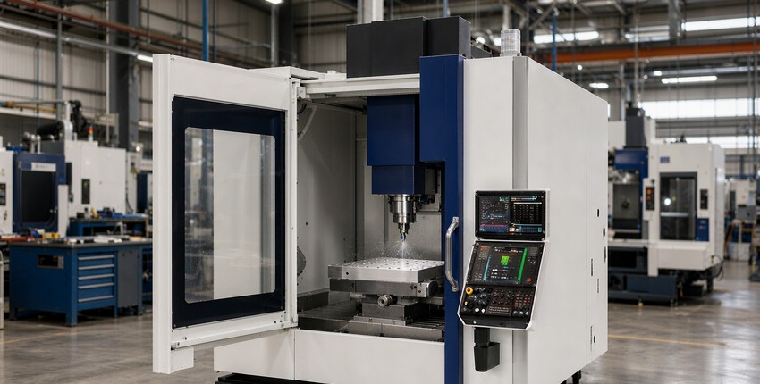
Where the numeric tables behind these ranges live: the tolerance and fit reference page covers IT grades and ISO 286 fits, and the surface finish reference page relates the roughness values that usually accompany form callouts. The machines that produce this class of geometry are listed on the equipment page.
Frequently Asked Questions
Do form tolerances ever reference a datum?
No. Straightness, flatness, circularity and cylindricity are always self-referencing. If a feature control frame on one of these symbols shows a datum letter, the drawing has an error or is using a nonstandard convention that should be clarified before quoting.
Is flatness included automatically when I specify parallelism?
Not exactly. A parallelism zone of two planes does bound the surface's deviation from the datum orientation, and a perfectly parallel surface could still be wavy inside that zone. If waviness matters for sealing, add an explicit flatness callout. The tighter of the two requirements governs each aspect.
Why did my roundness measurement differ between the supplier's roundness tester and our CMM?
Evaluation method and point density. Roundness testers rotate continuously and filter the profile; CMM roundness depends on how many points were sampled per cross-section and which fitting algorithm was chosen, least squares or minimum zone. Agree on the method, the filter and the reference algorithm at quotation, and the numbers will agree. For how we verify these callouts on the floor, see inspection and QC.
Can a V-block and dial indicator verify roundness?
It can screen it, not verify it. The V-block reading mixes true roundness with lobing artifacts, so a part can look good or bad depending on the included angle. For callouts at 0.005 mm or tighter, use a roundness tester or a CMM with adequate sampling.
What causes roundness failures on thin-wall machined parts?
In our experience the top cause is residual stress relaxation after heavy roughing, followed by clamping distortion and cutting heat. The remedy is process-level: stress relief between operations, thermal soak before finish cutting, light finishing cuts and controlled coolant. Blaming the machine or the tool usually does not fix it. How these callouts sit inside the full tolerance system is summarized on our tolerance standards page.
Can KGL hold 0.005 mm form tolerances on my parts?
On compact features in stable materials, yes, and our Zeiss CMMs and roundness tester verify them with full reports. The honest qualification is that feasibility depends on size, wall thickness and material. Send the drawing and we will confirm the achievable values, the process route and the price together.
This article is general engineering guidance, not a binding manufacturing guarantee. Tolerance feasibility, inspection methods and reporting formats are confirmed per part based on drawings, materials, quantities and process review. Request a formal quotation for part-specific terms. (c) 2026 KGL. All rights reserved.
Related Articles
More from the Inspection & Metrology series.
Have a project in mind?
Send drawings to kgl@kglmfc.com or request a quote. We respond within 24 hours.
Request a Quote