Orientation Tolerances: Parallelism, Perpendicularity and Angularity
How orientation tolerances work on CNC drawings: why all three need datums, what the tolerance zones look like, how perpendicularity is actually measured on a CMM and with a V-block, and a robot brake shaft case with post-anodize callouts.
Key Takeaways
- Every orientation tolerance references a datum. Without a datum letter in the feature control frame, a parallelism or perpendicularity callout has no meaning.
- The datum order in the frame is the assembly order. Primary datum first contact, secondary second, tertiary last, following the 3-2-1 locating principle.
- A perpendicularity callout with a diameter symbol creates a cylindrical tolerance zone around the axis, which controls the tilt in every direction at once, not just in one viewing plane.
- For short parts with a length-to-diameter ratio under 3:1, a V-block and dial indicator check can track a CMM within about 0.005 mm, but only after the correlation has been proven on real parts.
- Surface treatments change geometry. If tolerances apply after anodizing or plating, say so on the drawing and budget the film growth in the process, or the callout will be argued about at acceptance.
Form tolerances describe a feature against itself. Orientation tolerances describe a feature against something the design trusts. That single difference changes everything downstream: the callout needs a datum, the inspection needs the datum feature present, and the result depends on which datum is listed first.
This article covers the three orientation characteristics from the GD&T basics overview: perpendicularity, parallelism and angularity. It explains the tolerance zones, shows how each is measured both on a CMM and with conventional tools, and works through a real robot-joint brake shaft whose orientation callouts had to survive hard anodizing.
1. The rule all three share: no datum, no meaning
Parallelism, perpendicularity and angularity all answer the same kind of question: how far may this feature tilt, relative to a datum? Remove the datum and the question dissolves. A face cannot be "parallel" in isolation; it is parallel to something.
That is why every orientation feature control frame carries at least one datum letter. It is also why orientation callouts cost more to inspect than form callouts: the datum features must be measured or fixtured, and the measurement of the toleranced feature is referenced to them. The datum is not decoration. It is the anchor the whole callout hangs from.
| Characteristic | Angle to datum | Tolerance zone | Typical use |
|---|---|---|---|
| Perpendicularity | 90 degrees | Two planes, or a cylinder for an axis | Machining faces against mounting faces, bores against faces |
| Parallelism | 0 degrees | Two planes or lines parallel to the datum | Rails, sliding faces, spacer faces |
| Angularity | Any basic angle | Two planes at the basic angle | Dovetails, wedges, angled port faces |
One reading note: angularity always pairs with a basic dimension, the theoretically exact angle shown in a rectangle on the drawing. The basic angle itself carries no tolerance. The angularity callout carries all of it.
2. Perpendicularity: the axis case is the important one
On planar faces, perpendicularity works like a 90-degree version of parallelism: the surface must stay between two planes held at a right angle to the datum.
The case that matters most in CNC work is the axis version. When the callout applies to the axis of a bore or a pin and carries a diameter symbol, the tolerance zone is a cylinder of the stated diameter, oriented exactly perpendicular to the datum. The produced axis must fall inside that cylinder. This is a stronger and more useful statement than a width zone, because it controls the tilt in every direction simultaneously, not just in the plane of the drawing view.
This is also where the size-plus-geometry interaction becomes visible. A bore can be within its diameter limits at every point and still tilt enough to fail perpendicularity. The size limit controls the surface; the perpendicularity callout controls where the axis points. On precision assemblies, that axis callout is what keeps a press-fit pin square to its base or a bearing bore square to its mounting face.
3. Parallelism and angularity in practice
Parallelism protects function wherever two surfaces slide or space against each other: guide rails, gib faces, spacer shoulders, fixture clamps. Its failure mode is wedge-shaped clearance, a part that fits at one end and binds at the other.
Angularity handles every angle that is not 0 or 90. Dovetail ways, locating wedges, angled port faces on manifolds, chamfered locating faces on aerospace fittings. The inspection principle is identical to parallelism, only the reference angle changes, which is why some inspectors describe angularity as "parallelism at an angle".
Both share a practical trap: measuring them without honoring the datum. If an inspector measures the angle between two faces with a protractor or an inclinometer, neither face is the datum and the result is not the callout. The datum face must be simulated, on a plate, in a fixture, or in CMM software, before the reading means what the drawing says.
4. Measuring perpendicularity: CMM and the conventional fallback
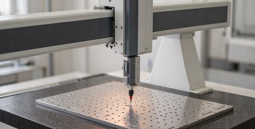
On a CMM, the axis-and-plane case is routine: sample the bore with enough points to fit an axis, sample the datum face with a point pattern that captures its orientation, and let the software evaluate the angular deviation of one relative to the other. For a 32 mm bore, a typical routine takes three cross-sections of eight points each, 24 points total, and fits a least-squares cylinder. A full evaluation of that kind on one part runs about 12 minutes including setup.
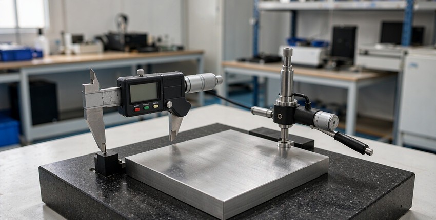
The conventional method for shaft-type parts is the V-block method. The shaft sits in a precision V-block on a grade-00 granite plate, a lever-type dial indicator with 0.001 mm resolution touches the reference face or a precision square anvil, and the part is rotated through 180 degrees. The perpendicularity error is read from the half-difference of the indicator travel: if the needle swings from plus 0.006 to minus 0.006 mm across the rotation, the perpendicularity error is about 0.012 mm.
That shortcut is legitimate for short parts, and it is dangerous to generalize it blindly. Our internal validation across 120 parts showed the V-block result tracking the CMM truth within about 0.005 mm, but only for parts with a length-to-diameter ratio under 3:1. Longer parts tilt in ways a single V-block setup does not capture, and lobed or thin parts distort under the contact force. The reliable pattern is a dual-track one: prove the fast method against the CMM on the first 30 pieces of a new part, log the offset, and only then let the production line run routine checks with conventional tools while the CMM handles first articles and sampling.
5. Case: a robot-joint brake shaft with post-anodize callouts
A brake shaft for a robot joint braking system shows how orientation tolerances behave on a real production part, and what happens when a surface treatment sits between machining and inspection.
The part is a flanged multi-diameter shaft machined from 7075-T6 aluminum. The flange carries eight through holes of 2.4 mm diameter on a 20.5 mm bolt circle, the center carries a 32 mm bearing bore, and the shaft extension connects to the brake disc. The whole part is hard anodized with a 0.1 mm film, and the drawing states that every tolerance applies to the final, post-anodize dimensions.
Six geometric callouts appear on the drawing. The axis of each journal must be perpendicular to datum A, the right end locating face, and to datum B, the left shoulder, within 0.02 mm. The 32 mm bearing bore must be perpendicular to the centerline datum C within 0.015 mm, the strictest callout on the part. The flange top face must be parallel to datum C within 0.02 mm, the side mounting face parallel to datum B within 0.02 mm, and the eight-hole pattern must hold a position of 0.04 mm relative to datum A.
The datum order is not arbitrary. Datum A is the face that seats first against the joint housing during assembly: it is the largest stable face and the bearing press-fit bears on it, so it minimizes rocking. Datum B handles axial location and flange thickness control. Datum C, the bearing bore axis, anchors the rotating geometry that the eight-hole pattern and the flange face relate to. The frame order A, B, C mirrors the way the part is bolted into the joint, which is exactly what a datum sequence should do under the maximum stable contact principle.
The anodize question became the acceptance story. The customer challenged the 0.015 mm perpendicularity called on post-anodize dimensions: would the growing oxide film destabilize the geometry? The response was threefold. First, data: CMM comparisons across 12 production batches, before and after anodizing, showed a mean perpendicularity shift under 0.003 mm, with process capability indices between 1.67 and 2.31, meaning the anodize effect consumed about one fifth of the tolerance band. Second, transparency: first-article reports, SPC charts and tool life records were opened to the customer, including a remote audit. Third, demonstration: the customer's quality engineer visited, watched the CMM measure the 32 mm bore, and saw the report print 0.008 mm on the spot. The customer withdrew the request for resident inspection and moved to incoming sampling. Data ended the argument faster than any explanation could.
The process route behind those numbers is worth naming, because none of it is exotic: a mill-turn complete machining in one setup, a pre-machining allowance that compensates the anodic film growth, and a closed-loop dimensional check with a high-precision height gauge after anodizing. Batches have held parallelism and perpendicularity within 0.02 mm consistently. The full lesson for buyers: when tolerances must hold after a surface treatment, the drawing should say so explicitly, and the shop's process must budget the film thickness rather than hope it averages out.
6. Why datum order changes the reported number
Swap the datum order in a frame and you change the measurement, even with identical tolerance values. The primary datum is simulated first and constrains three degrees of freedom, typically plane contact. The secondary constrains two more, and the tertiary fixes the last rotation. Each earlier datum absorbs the part's variation, so the toleranced feature is evaluated against whatever the earlier datums left behind.
A face measured parallel to datum A alone can report one number; the same face measured parallel to A then B can report a different number, both correct. This is why the datum sequence on the drawing should follow the assembly sequence, and why inspection fixturing should mimic assembly contact. When a supplier and a customer measure the same callout with different datum simulation, both sets of numbers are honest and neither matches. Agreeing on the datum order at quotation is cheaper than reconciling reports after delivery.
7. A buyer's checklist for orientation callouts
| Check | Why it matters |
|---|---|
| Every orientation callout has a datum letter | Without it the callout is unmeasurable and will be quoted defensively |
| Datum order matches assembly contact order | The reported number then predicts assembly behavior, not just laboratory geometry |
| Axis callouts carry the diameter symbol where tilt is multi-directional | A width zone controls one plane; a cylindrical zone controls all directions |
| Tolerances after coating are marked as final-size or pre-coat | Film growth of 5 to 50 µm per side is real geometry, not noise |
| The inspection method is agreed, CMM routine and gauge plan included | Method differences, not part differences, cause most acceptance disputes |
The industry context for this class of part, tight orientation callouts on rotating assemblies, appears across our robotics work and in aerospace components described on the aerospace page. The CMM fleet that verifies these callouts is listed on the equipment page, and the numeric grades behind callouts like 0.02 mm are cross-referenced on the tolerance and fit reference page.
Frequently Asked Questions
What is the difference between perpendicularity and flatness on a face?
Flatness is self-referencing and controls waviness alone. Perpendicularity on a face controls how the entire surface is oriented relative to a datum, and its zone is two planes at exactly 90 degrees to that datum. A face can be perfectly flat and badly non-perpendicular, or square to the datum yet wavy. They bound different failure modes and are often both specified on functional faces.
Why does a perpendicularity callout on a hole have a diameter symbol?
Because the tolerance zone is a cylinder around the axis. The diameter symbol says the stated value applies in every direction around the axis, not just in the plane of the drawing view. Without it, the zone is two parallel planes and the tilt is only bounded in one orientation.
Can perpendicularity be checked without a CMM?
Yes, within limits. For short shafts, a V-block, granite plate and 0.001 mm lever indicator give a usable reading by rotating the part 180 degrees and taking the half-difference of indicator travel. The method tracked our CMM within about 0.005 mm on parts with a length-to-diameter ratio under 3:1. Long, thin or lobed parts need the CMM.
Does hard anodizing really affect geometric tolerances?
It can. Hard anodize grows roughly 25 to 50 µm per side, about half built up and half penetrating. On a 0.015 mm perpendicularity callout, uncontrolled film growth could consume the entire band. The solution is process control: pre-machining compensation, batch SPC on post-anodize geometry, and final inspection after treatment. Our 12-batch data showed a mean shift under 0.003 mm with CPK between 1.67 and 2.31.
Why does the datum order in the frame matter if the tolerance value is unchanged?
Because each datum absorbs variation in sequence. The primary datum plane takes up contact first, the secondary takes orientation, and the tertiary fixes rotation. Changing the order changes what variation the toleranced feature is judged against, so the same surface can report different values under different datum sequences. Order should follow assembly.
Can KGL inspect orientation callouts on parts with coatings applied?
Yes. Our standard route machines with film-growth compensation, applies the treatment, and performs final CMM inspection on the post-treatment part, with a full report per batch. Send the drawing with the callouts and the coating specification, and we will confirm the achievable values and the inspection plan at quotation.
This article is general engineering guidance, not a binding manufacturing guarantee. Tolerance feasibility, inspection methods and reporting formats are confirmed per part based on drawings, materials, quantities and process review. Request a formal quotation for part-specific terms. (c) 2026 KGL. All rights reserved.
Related Articles
More from the Inspection & Metrology series.
Have a project in mind?
Send drawings to kgl@kglmfc.com or request a quote. We respond within 24 hours.
Request a Quote