Interface Fits in Semiconductor Tool Frames: Tolerances We Hold
How reamed dowel holes, datum faces and mounting pads set alignment in semiconductor tool frames, which fits to specify, how flatness and hole position are held across setups, and how every interface feature is verified on the CMM.
If a semiconductor tool frame lands on the assembly floor and the submodule above it will not drop in without shims, the problem is almost never the bolts. It is the interface features: the reamed dowel holes, the machined datum faces and the flat mounting pads that decide where every module sits. We hold ±0.005 mm on machined interface features as our standard band. Tighter bands, at ±0.002 mm, are available only on specific features machined on our five-axis centers, verified with full CMM inspection and noted with those conditions on the report. Here is how we get there, and what we check.
1. Which interface features actually set alignment?
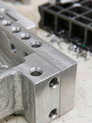
Bolts clamp. They do not locate. In a machined frame for semiconductor equipment (see the parts we regularly build for this industry), position comes from three families of features, and each carries its own tolerance logic.
Dowel holes and pins set true position. A typical frame design uses two or more reamed dowel holes per interface, paired with hardened pins. Drawings usually call an ISO sliding fit, an H7 bore against a g6 pin, so the module slides in by hand and still cannot wander. Where a pin never needs removal, an interference fit such as H7/p6 keeps it permanently seated.
Datum faces set orientation. One machined face acts as the primary reference, a second face or edge as secondary. The flatness and finish of those faces decide whether the mating part rests against metal or rocks on its own bolt pattern.
Mounting pads carry load. Machined pads keep clamping stress away from the precision features, so tightening bolts does not bend the interface you just measured.
A frame can carry hundreds of fasteners. If the dowels and datums are right, assembly is routine. If they are not, no amount of bolt torque recovers alignment.
2. Why do flatness and parallelism matter as much as hole position?
Hole position gets the attention, but flatness quietly decides whether a frame works. When a cover or module plate is bolted onto a face that is not flat, the bolts pull that plate into the error. The clamped assembly now carries built-in stress, and features you measured loose on the table move once the bolts go tight.
Callouts we see on semiconductor frame drawings run from 0.01 to 0.02 mm flatness on mid-size mounting faces, with parallelism between opposed pads around 0.02 mm. Thin plates show the effect faster than thick ones. The fix is sequence, not heroics: rough both sides first, let the plate move while there is still stock to correct, then finish faces and bores in one clamping where the geometry allows it.
Fixture design belongs in the same discussion. Clamping a thin frame plate flat on the machine, then releasing it, is how a flat plate leaves the machine and a bowed plate arrives at inspection.
3. How do we hold position on dowel and bolt patterns?
Position error stacks from every source between the tool tip and the CMM: machine geometry, thermal drift, tool pressure and fixturing. The biggest single lever is setup count.
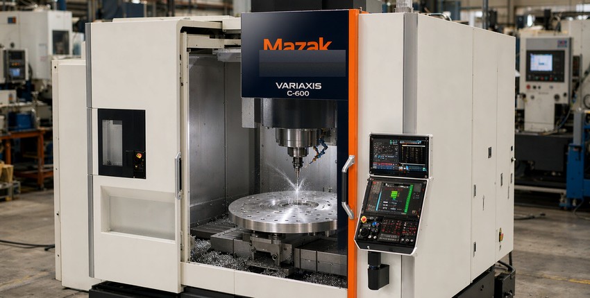
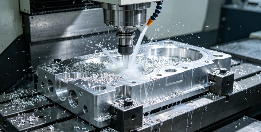
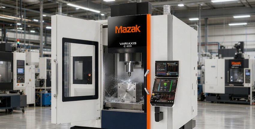
Our shop runs 100+ CNC machines, including 11 five-axis centers such as the Mazak VARIAXIS C-600 and j-500/5X. On frame plates that fit the envelope, we finish dowel bores, datum faces and the bolt pattern in one setup, so those features share the same machine reference. Larger plates move to our 3-axis mills: we machine a datum face first, re-datum the second operation from that finished face, and verify the handoff on the CMM.
For H7 bores we pilot, rough bore, then finish bore or ream and leave a small controlled stock for the finishing pass. Interpolated bores get a spring pass so tool deflection does not steal position.
The numbers we commit to: ±0.005 mm on machined features across the shop as the standard band. ±0.002 mm only on specific features on five-axis work, verified with full CMM inspection, with those conditions noted on the report so nobody assumes they apply to every dimension. Where a drawing calls a class of fit rather than a band, we machine the reamed bore to that callout.
4. What does stress relief change in aluminum frames?
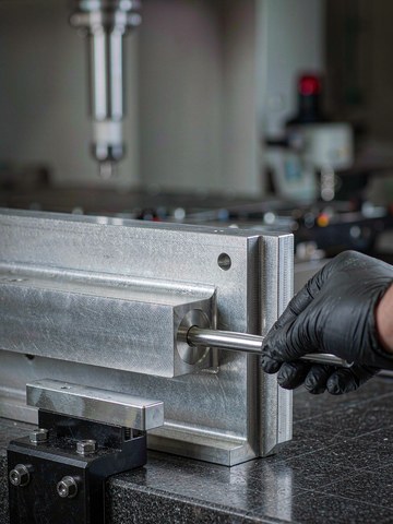
Most semiconductor frames are machined from aluminum: 6061 for general structure, 7075 where stiffness matters, MIC-6 cast plate for bases that should arrive flat and stay flat (materials by component type are covered in our semiconductor materials guide). Aluminum plate carries locked-in stress from rolling, extrusion or casting. Cut one side heavy and the plate moves as that stress releases.
The sequence that works: rough all sides, stress relieve, then finish. The part does its moving while we can still correct it, not after final inspection. Even on cast aluminum plate we keep that discipline on heavy stock removal, because a base that drifts 0.05 mm after finishing is a base that gets re-machined.
Thermal discipline sits in the same paragraph. Long finishing cuts on aluminum reward a warm machine and a patient operator: run the warm-up cycle, keep coolant flow steady, and measure the part after it settles rather than the second it leaves the fixture.
5. How are interface fits verified and reported?
A fit you cannot verify is a claim, not a tolerance. Verification is planned before the first chip is cut: every dimensioned interface feature on the drawing gets a measurement method assigned.
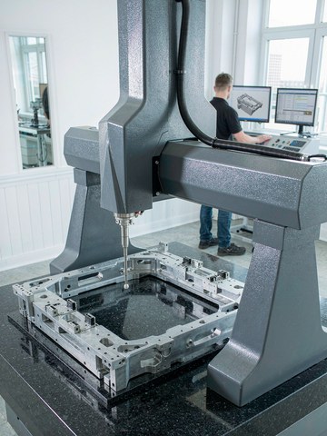
At the machine, operators check bores with pin gauges and faces with indicators during the run. The record comes from the CMM lab. We inspect on Hexagon and Zeiss bridge CMMs with 0.0015 mm machine accuracy, part of 40+ inspection instruments. Hole patterns are reported as position results against the drawing datums, flatness per face, bore diameter and form per bore.
Every dimensioned feature appears on the inspection report that ships with the part, so your assembly team sees what we measured, feature by feature, before anything is bolted together. First articles follow the same workflow, and fit bands are confirmed per part as described on our tolerance standards page. For how parts stay cleanroom-ready between final inspection and packaging, see our cleanroom machining guide.
From Our Shop Floor: A 400 x 300 mm Frame Base Plate
A semiconductor equipment frame base plate shows the sequence we use on large interface parts. The blank is 6061-T6, 400 x 300 x 25 mm, machined on a Mazak VARIAXIS C-600 five-axis center. A vacuum chuck plus side clamps hold the plate through a single setup that finishes all six faces. Rough milling leaves 1 mm of stock, then the plate sits in a temperature-controlled room for 24 hours so residual stress can move before finishing. Measured on the Zeiss CMM, the finished plate came in at 0.006 mm flatness on the datum face against a 0.01 mm drawing callout, and the four Ø8H7 locating holes measured 0.008 mm true position against 0.01 mm. Cycle time runs 6.5 hours including 30 minutes of full CMM inspection, and the plate passed first-piece submission.
Case Study: Interface Plates for a Lithography Equipment Frame
The project: interface plates for a semiconductor lithography equipment frame, from the world's leading semiconductor lithography equipment maker. The part is a 6061-T6 mounting plate, 420 x 280 x 25 mm, with four Ø8H7 locating holes held to 0.01 mm true position, a 0.01 mm flatness callout on the datum face and 0.015 mm parallelism. We machine it on a Mazak VARIAXIS C-600 in one five-axis setup with roughing and finishing split apart and a 24 hour stress relief dwell between them. Measured results on the Zeiss CAPTUM CMM: 0.007 mm flatness, 0.008 mm true position and 0.011 mm parallelism, with process capability at or above CPK 1.67. The order covered 300 pieces delivered in weekly batches across four weeks, DFM feedback returned within 24 hours, and a full year of shipments closed with no returns. Client details stay anonymous, and a reference is available under NDA.
Frequently Asked Questions
What tolerance can you hold on dowel holes and interface features?
±0.005 mm on machined features is our standard band. ±0.002 mm is available only for specific features on five-axis work, verified with full CMM inspection, with those conditions noted on the report. Fits such as H7 are machined to the drawing callout.
Which fit should I specify for locating pins in a tool frame?
Most frame designs pair an H7 reamed bore with a g6 or h6 pin for a hand-sliding location, and use an interference fit such as H7/p6 where the pin never comes out. If your drawing only says ream for dowel, we confirm the fit class with you before machining.
Can you keep a hole pattern aligned across two setups?
Yes. We finish a datum face first, re-datum the second operation from that face, and verify the handoff on the CMM. Where the plate fits the envelope of our five-axis centers, the whole pattern is finished in one setup and re-clamping error never enters.
How do you verify flatness on a large frame plate?
On the CMM. Our Hexagon and Zeiss bridge machines measure flatness per face at 0.0015 mm machine accuracy, and the report shows a result for every dimensioned face, not a pass or fail stamp.
What should the drawing include for an interface quote?
Datums, the fit class or tolerance band for each locating feature, position and flatness callouts, material, and any finish or heat treat notes. With complete 2D and 3D files, quotes come back within 24 hours, and there is no minimum order for prototype parts.
This article is general engineering guidance, not a binding manufacturing guarantee. Tolerances are confirmed per part based on drawings, materials and process review. Request a formal quotation for part-specific specifications. (c) 2026 KGL. All rights reserved.
Related Articles
More from the Semiconductor series.
Have a project in mind?
Send drawings to kgl@kglmfc.com or request a quote. We respond within 24 hours.
Request a Quote