Vacuum Chamber Parts: What Flatness and Surface Finish Do Sealing Faces Actually Need?
Where vacuum chamber leaks actually start, the flatness and Ra numbers that make an O-ring seal work, the machining sequence that keeps sealing faces flat after the part leaves the machine, what to check on the supplier's inspection report before you accept the parts, and a documented lot from our shop floor where the customer re-measured the same flatness and roughness and accepted the batch with zero nonconformance reports.
Key Takeaways
- Most vacuum chamber failures start at the sealing face, not inside the chamber. The two numbers that decide the seal are flatness of 0.05 mm or better per 100 mm of diameter and a seal path roughness of Ra 0.8 µm or finer.
- Sealing faces warp after machining because of residual stress, thin unsupported sections and clamping pressure, so distortion control is a sequence of roughing, stress relief and a final single-setup finishing pass, not one heroic cut.
- Leave the seal face and O-ring groove bare machined and anodize only external surfaces unless the drawing says otherwise. The anodized layer adds thickness and can be slightly porous.
- Judge a supplier's report on the features that make the seal work: sealing face flatness, roughness readings taken on the seal path itself, groove diameter and width, and bolt hole position against the flange pattern.
- A useful RFQ carries the 2D drawing with flatness, roughness and groove callouts, the 3D model, alloy and temper, the sealing method, and whether the leak rate applies to the machined part or the welded assembly. Complete files get a quote back within 24 hours.
- Repeatability is the real mark of a seal face supplier. On lot 047 the customer re-measured a 10 percent sample under AQL 1.5 and got flatness 0.007 mm max and Ra 0.38 micron max, against our 0.008 mm and 0.40 micron. The batch was accepted with zero nonconformance reports.
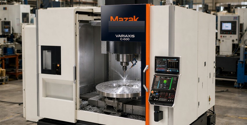
Most vacuum chamber failures do not start inside the chamber. They start at the sealing face. For machined aluminum or stainless vacuum chamber parts, the numbers that matter are a sealing face flatness of 0.05 mm or better per 100 mm of diameter for O-ring grooved lids, a surface roughness of Ra 0.8 µm or finer on the seal path, and a machining process that leaves no residual stress to warp the face after the part leaves the machine. This guide explains where those numbers come from, which features on a chamber drawing drive the cost, and how a machine shop should verify them before shipping.
1. Why do vacuum chamber sealing faces fail?
A vacuum seal works by compressing an elastomer O-ring between two machined surfaces. If the sealing face is wavy, the O-ring cannot fill every gap and the chamber leaks or pumps down slowly. Three machining problems cause most of these failures. First, residual stress in the blank: a thick aluminum plate that was face milled in one aggressive pass will bow as material is removed. Second, thin sections: a lid with a large unsupported area flexes under clamping pressure and comes out of the fixture with a dish shape. Third, finish: deep tool marks or chatter on the seal path give the O-ring leak paths that no amount of bolt load can close. All three are predictable, which means all three can be engineered out.
2. How flat should a vacuum chamber part be?
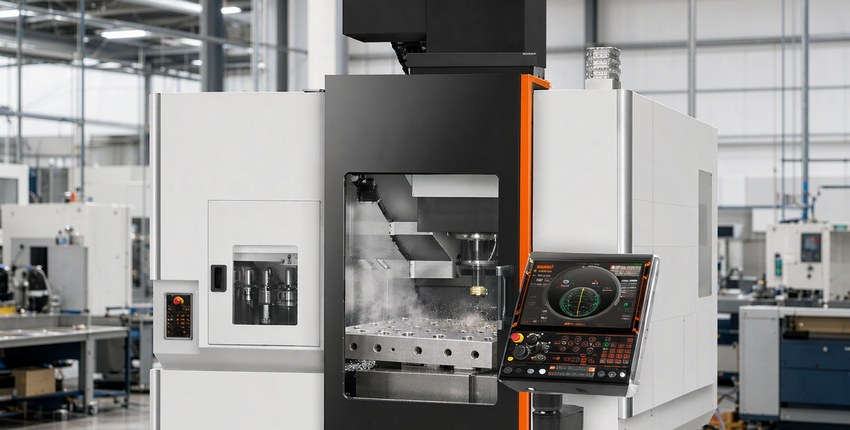
For a grooved O-ring seal in the ISO-KF, CF and similar style ranges, a practical target is flatness of 0.05 mm or better across the sealing face, and tighter as the diameter grows. As a reference point, we routinely hold 0.02 mm flatness on sealing faces of a few hundred millimeters, and on 5-axis setups with stress-relieved blanks and a full CMM verification we can work to ±0.002 mm on critical features when the drawing calls for it. Our standard machining tolerance is ±0.005 mm, and flatness on a chamber lid is usually a form callout rather than a size tolerance, so check your drawing's feature control frame. For what each form symbol controls, see our guide to form tolerances. If the drawing only gives a plus or minus size for the lid thickness, the flatness of the face is up to the process, and that is exactly where cheap quotes go wrong.
3. What surface finish does a seal path need?
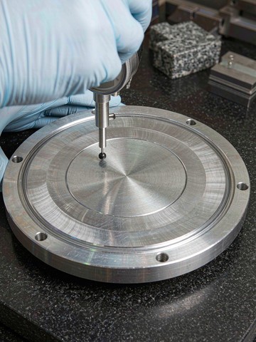
For elastomer O-rings, a sealing face finish of Ra 0.8 µm or finer is a safe default, and Ra 0.4 µm is common on high vacuum work. The finish also needs to be consistent in direction: a fine, circular lay left by a slow finishing pass seals better than random chatter marks at the same Ra number. Two machining choices get you there. A dedicated finishing pass with a fresh tool and light depth of cut, around 0.1 to 0.2 mm, and a machine that is thermally settled before that pass starts.
| Feature | Practical target for an O-ring sealed chamber |
|---|---|
| Sealing face flatness | 0.05 mm or better per 100 mm of diameter, tighter as the diameter grows |
| Seal path roughness | Ra 0.8 µm or finer; Ra 0.4 µm common on high vacuum work |
| Finishing pass | Fresh tool, 0.1 to 0.2 mm depth of cut, thermally settled machine |
| O-ring groove | Diameter and width to drawing, CMM verified |
If your part will be anodized, note that anodizing adds thickness and can be slightly porous, so many vacuum parts leave the seal face bare machined and anodize only the exterior. For the coating options and what each does to dimensions, see our overview of anodizing types and the wider surface finish menu. State the intent on the drawing rather than leaving it to assumption.
4. Which machining steps prevent post-machining distortion?
Distortion control is a sequence, not a single operation. A typical flow for an aluminum chamber lid looks like this. Rough both sides with generous allowance, then stress relieve, then semi-finish, then finish the sealing face last in one setup, or on a 5-axis center in the same coordinate system as the bolt holes. Fixturing matters as much as programming: clamping a large thin lid directly on its face and cutting the other side will print the fixture pattern into the part. Vacuum chucks, soft jaws bored to the part radius and low clamping forces spread the load. For chamber bodies with long, thin-wall sections, the same logic applies and we have written about it in more detail in our thin wall machining guide.
5. What should you check on the supplier's inspection report?
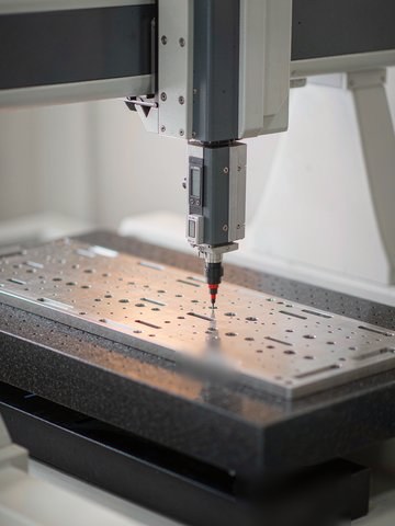
Ask for the numbers on the features that make the seal work, not just overall dimensions. A serious report for vacuum chamber parts should include flatness of the sealing face, surface roughness readings taken on the seal path itself, O-ring groove diameter and width, and the position of bolt holes against the flange pattern. We verify these on Hexagon and Zeiss bridge CMMs with 0.0015 mm accuracy, and every part ships with an inspection report you can match line by line to the drawing. For how that verification is organised, see our CMM and first article workflow. If your chamber needs helium leak testing or bake-out qualification, those tests normally happen at your facility or a test house, so agree in advance which party runs them and what documentation the machined parts must carry.
6. Which materials suit vacuum chamber machining?
Aluminum 6061-T6 and 6082 cover most research and industrial chambers because they machine fast, seal well and outgas acceptably after cleaning. 5083 is a good choice for larger welded body sections, and 2219 is used where a welded, cryogenic-capable build is specified. Stainless 304 and 316 suit bake-out and UHV work; 316L is the default when corrosion resistance matters, and 17-4PH appears where the flange also carries structural load. One caution: PEEK and other polymers appear inside vacuum systems as insulators and fixtures, but their outgassing behavior is very different from metals, so treat polymer vacuum parts as a separate sourcing topic.
| Material | Where it fits in vacuum work |
|---|---|
| Aluminum 6061-T6 / 6082 | Most research and industrial chambers; fast machining, seals well after cleaning |
| Aluminum 5083 | Larger welded body sections |
| Aluminum 2219 (T851) | Welded, cryogenic-capable builds |
| Stainless 304 / 316 / 316L | Bake-out and UHV work; 316L where corrosion resistance matters |
| Stainless 17-4PH | Flanges that also carry structural load |
7. What information should an RFQ for vacuum chamber parts include?
The fastest way to a useful quote is to give the drawing and the operating context. Include the 2D drawing with flatness, roughness and groove callouts, the 3D model, the base alloy and temper, whether the part is welded up or machined from solid, the sealing method, and any cleaning or packaging requirements. Note whether your leak rate specification applies to the machined part alone or to the welded assembly. With complete 2D and 3D files we return quotes within 24 hours, there is no minimum order quantity, and single-piece sampling is supported. For background on our quality system, see our quality overview, and the quote page lists what to attach so the first answer comes back complete.
8. From our shop floor: a 6061-T6 vacuum chamber lid, lot 047
Part VCL-280-6061-T6-Rev.C is a vacuum chamber lid machined from a 320 mm diameter, 32 mm thick 6061-T6 (T651) stress-relieved aluminum plate. The finished sealing land is only 3.5 mm thick, thin enough that clamping force on its own can distort it, so the workholding decision had to be made before the toolpath was written. The job ran in four operations:
- Op-10: rough turn OD, face and recess, leaving 0.8 mm of stock on the sealing surface.
- Op-15: stress relief at ambient temperature, 24 hours at 20 plus or minus 2 degrees C, before any finishing cut.
- Op-20: finish turn the sealing face in a single pass, 0.15 mm depth of cut, 180 m/min cutting speed, 0.08 mm per revolution feed, 8 percent synthetic coolant.
- Op-30: finish turn the OD and counter-bore to print.
The lid was held on a 250 mm porous vacuum chuck at 0.06 MPa. That pressure is low enough to support a light finishing pass but not high enough to print the chuck pattern into the sealing land, and no clamping distortion was measured on the land after release.
In-process checks were taken on the machine and confirmed on a Zeiss CAPTUM CMM:
| Checkpoint | Target | Measured | Instrument |
|---|---|---|---|
| Sealing-face flatness | 0.010 mm max | 0.008 mm | Zeiss CAPTUM CMM |
| Sealing-face roughness Ra | 0.50 µm max | 0.40 µm | Mitutoyo SJ-210 |
| OD diameter | 280.00 ± 0.03 mm | 280.014 mm | CMM |
| Counter-bore depth | 12.00 ± 0.05 mm | 12.02 mm | CMM |
CMM report CMM-2026-VC-047, recorded on 2026-10-11 at 20.1 degrees C.
The customer re-measured the same features on a 10 percent sample of lot 047 under AQL 1.5, general inspection level II. Maximum flatness across that sample came back at 0.007 mm and average flatness at 0.005 mm. Maximum roughness was Ra 0.38 µm, average Ra 0.34 µm. The lot was accepted with zero nonconformance reports. Hitting flatness and roughness inside the drawing limit on one part is a machining result. Repeating it across a lot, and having the buyer measure the same numbers we did, is a process result.
Frequently Asked Questions
What flatness can you hold on a vacuum chamber lid?
On sealing faces in the few-hundred-millimeter range we routinely achieve 0.02 mm flatness, and tighter values are possible on 5-axis setups with stress-relieved blanks and 100 percent CMM verification. Our standard tolerance is ±0.005 mm.
Do machined vacuum parts need to be anodized?
Not always. Anodizing adds a slightly porous layer, so many designs leave the seal face and groove bare machined and anodize only external surfaces. Follow your drawing, or tell us the service temperature and vacuum level and we will flag the risk.
Can you machine chambers from solid or only plates and flanges?
Both. We machine flanges, lids, ports and body sections from solid on our 100+ CNC machines, including 11 five-axis centers. Welded assembly and leak testing are normally handled by your integration partner; we supply the machined components with full inspection data.
What materials do you keep for vacuum work?
Aluminum 5083, 6061, 6082 and 2219 (T851), stainless 304, 316 and 17-4PH families, plus engineering plastics such as PEEK for internal fixtures. Material certificates are available on request.
How fast can I get first samples?
Quotes come back within 24 hours of receiving complete 2D and 3D files, and single-piece sampling is supported with no minimum order quantity.
This article is general engineering guidance, not a binding manufacturing guarantee. Tolerance feasibility, inspection methods and reporting formats are confirmed per part based on drawings, materials, quantities and process review. Request a formal quotation for part-specific terms. (c) 2026 KGL. All rights reserved.
Have a project in mind?
Send drawings to kgl@kglmfc.com or request a quote. We respond within 24 hours.
Request a Quote