CNC Machining for Farm and Earthmoving Equipment: Fits and Wear Life
Why farm and earthmoving parts are judged on fits and seal integrity: pin and bushing clearance, O ring bore finish, and the parts that fail first in service
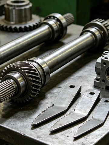
A combine harvester that stops in the middle of a two week weather window costs its owner far more than the failed part. That arithmetic is why farm and earthmoving equipment is one of the least forgiving sectors for machined components: the machine works in abrasive dust, takes shock loads that no bench test reproduces, sits idle for months, then returns to full load without a warm up. A part that measures perfectly on a granite table can still fail in the field, and a part that passed in year one can still refuse to install in year eight.
This guide works through the four things that decide whether a machined component survives that life: the fit philosophy behind interchangeability, the sealing and bearing interfaces that carry the hydraulics and drivetrain, the steels and heat treatments that resist abrasion and shock, and the setup discipline that keeps large parts accurate. It closes with the failure modes we see most often and the questions that make an RFQ answerable in one pass.
At a glance
- Interchangeability is a tolerance stack question, not a tolerance value. On a typical pivot joint the frame hole position, not the pin diameter, dominates the stack.
- Sealing bores fail on roundness, lead and finish long before they fail on diameter. A bore that measures 40.000 mm and carries a helical tool mark will still weep.
- Wear parts are usually case hardened, not through hardened. A tough core under a hard skin survives shock that a uniformly hard pin cannot.
- Spare parts business is a records business: heat numbers, fixture retention and program revisions decide whether a reorder matches the original batch.
1. Why Is Interchangeability the Real Specification?
A field technician replaces a pivot pin with a part from a box, using a hammer, a drift and whatever access the machine offers. There is no press, no oven, no alignment fixture and no time. Interchangeability therefore means something stricter than "made to drawing": any part from any batch must install into a joint that has already worn, in a frame that has already taken a knock, and must then hold for another season. That requirement is set at design time by the fit selected, and it is confirmed or destroyed by how the mating features are machined.
The fit arithmetic behind a field repair
Take a common joint: a 40 mm pivot pin in a bushing. The pin is called out at Ø40 h6, which is 40.000 to 39.984 mm. The bushing bore at Ø40 H8 is 40.000 to 40.039 mm. The clearance range is therefore 0 to 0.055 mm, and every part inside that range assembles by hand. So far the machining tolerance is doing its job.
Now put that joint in a welded bracket. The bracket hole position carries a general tolerance of plus or minus 0.5 mm, and the two lugs are welded on opposite sides of a frame. The pin now has to pass through two holes whose centrelines may be 1 mm apart. The 0.055 mm of clearance is irrelevant, because the stack is dominated by a term forty times larger. Field fitters solve this with a bigger hammer and a reamer, which is exactly the outcome a drawing review should have prevented.
The practical rules that come out of that arithmetic are unglamorous and effective. Machine the mating features in one setup so their relationship comes from the machine, not from a weld fixture. Where a weldment must carry the joint, machine the bores after welding and stress relief, not before. Where neither is possible, specify a self aligning element or a slotted interface and accept the movement deliberately instead of discovering it in the field.
2. What Do Hydraulic and Drivetrain Interfaces Actually Ask For?
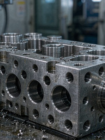
Hydraulic valve bodies, cylinder components and fittings live or die on sealing, and sealing is a system property: bore size, roundness, straightness, surface finish and the direction of the tool marks all contribute. An O ring seals by controlled squeeze, typically 15 to 25 percent of its cross section, and it needs a surface it can deform against. A bore that is on size but carries a helical feed mark gives the ring a path to follow, and the result is a slow weep that shows up as oil on a workshop floor rather than a burst hose on a warranty claim.
Three measurements matter more than the rest. Diameter holds the squeeze. Roundness and cylindricity decide whether the squeeze is even around the circumference, and we work to about 0.01 mm on sealing bores unless the design says otherwise. Surface finish on a dynamic seal sits around Ra 0.4 micrometres, with no spiral lead allowed; on a static face seal, Ra 0.8 is often enough. All three are verified on the CMM and a surface instrument, not inferred from the machine's own scale. The report follows our standard CMM first article workflow, so the numbers arrive attached to a part number rather than to a shift.
Bearing seats and gear interfaces
Drivetrain components transmit torque through hundreds of millions of cycles, and the machined interfaces decide whether that torque goes through the intended path. A bearing seat called at H7 with a shoulder squareness of 0.01 mm keeps the inner ring square to the shaft, which keeps the rolling elements loaded evenly. A housing with two bearing bores that are each perfect but 0.05 mm out of coaxiality will preload the shaft, run hot, and fail at the seal before it fails at the bearing.
Gear and spline interfaces add a second requirement: angular location. A keyway that is 0.02 mm off symmetry shifts the load to one flank. A spline with a runout of 0.03 mm produces a once per revolution vibration that the operator hears as noise and the warranty department sees as a returned gearbox. These are machined features, and they are cheap to control in process and expensive to correct after assembly.
| Interface | Typical call on the drawing | What it protects | Verification before shipment |
|---|---|---|---|
| Pivot pin to bushing | Ø40 h6 pin, Ø40 H8 bore, Ra 0.8 | Hand assembly, even after wear | Pin gauge plus CMM on first and last piece |
| O ring bore (dynamic) | Diameter within 0.02 mm, roundness 0.01, Ra 0.4, no lead | No weep at operating pressure | CMM plus surface instrument, lead check on a sample |
| Bearing seat | H7 bore, shoulder squareness 0.01, coaxiality 0.02 between bores | Bearing life, seal life, noise | CMM with coaxiality evaluation, not two separate diameters |
| Keyway or spline | Symmetry 0.02, runout 0.015 | Load sharing, vibration | CMM plus functional gauge |
| Cylinder rod | Ra 0.2 to 0.4, straightness 0.05 per metre, roundness 0.005 | Rod seal life, chrome adhesion | Profile measurement plus CMM on a sampling basis |
3. Which Materials Survive Dirt, Shock and Fertilizer?
The drivetrain runs on alloy steel because toughness matters more than hardness. 42CrMo4, familiar as AISI 4140, in the quenched and tempered condition at 28 to 32 HRC is the default for shafts and pins that must absorb shock without cracking. Where the surface needs to resist abrasion as well, the specification moves to a case hardening grade such as 20MnCr5, carburized to a case depth of 0.6 to 0.9 mm and hardened to 58 to 62 HRC, leaving a tough core to carry the bending load.
Induction hardened pins deserve a separate mention because they are so often over specified. A pin with a 50 to 55 HRC case over a 2 to 4 mm depth and a 30 to 35 HRC core will outlast a pin that is hard all the way through, and when it does fail it bends rather than shatters. The distinction matters in the field: a bent pin can be driven out, a shattered one takes the housing with it.
Structural parts follow a different logic. Weldments in S355 or Q345 carry frames and brackets, and they are machined after stress relief because welding locks in distortion that no amount of care at the machine will remove. Wear plates in 65Mn or a quenched and tempered abrasion resistant plate are usually cut and ground rather than milled, because hardness above 45 HRC turns a milling operation into a slow grinding operation with a poor surface.
Stainless appears wherever fertilizer, slurry or washdown chemicals attack plain steel: fittings, fastener hardware, exposed linkages and sensor brackets. The selection rule is to match the grade to the chemistry it actually sees, then check that the grade machines to the finish the seal needs. 316L handles chlorides and most fertilizer solutions; 304 is adequate for clean washdown but pits in chloride rich slurry, and the difference shows up as brown staining in the first season.
| Material | Condition | Hardness | Typical part | Machining consequence |
|---|---|---|---|---|
| 42CrMo4 (4140) | Quenched and tempered | 28 to 32 HRC | Shafts, pins, hubs | Pre-hardened, so plan insert grade and depth of cut up front |
| 20MnCr5 (5120) | Carburized after machining | 58 to 62 HRC case | Gears, splines, cams | Cut soft, leave 0.3 mm for growth and distortion, no finished bores before heat treat |
| 34CrNiMo6 (4340) | Quenched and tempered | 30 to 35 HRC | High torque shafts | Tough and stringy, so lower surface speed and heavier feed to avoid work hardening |
| 65Mn or wear plate | Hardened and tempered | 45 to 52 HRC | Wear plates, blades | Grind or laser cut rather than mill, expect burr control by hand |
| ADI | Austempered | 250 to 300 HB | Bushings, hangers | Cast skin is abrasive, so take a full cleanup pass and locate from a machined datum |
| 316L | Annealed | Around 80 HRB | Fittings, hardware | Work hardens, so keep the tool cutting and never rub |
4. What Changes When the Part Is Large?
Large parts accumulate error differently, and most of that error has nothing to do with the position of the spindle. A one metre steel housing moves about 12 micrometres for every kelvin of temperature change. A shop floor that swings from 16 to 26 degrees over a shift moves that housing 0.12 mm, which is twenty times the tolerance on a bearing seat. This is why finish machining of critical features happens in a temperature controlled area and why the CMM reports the temperature at which it measured.
Clamping is the second source. A thin walled housing that is clamped hard enough to stop chatter is also clamped hard enough to spring back when the clamps release, so a bore that measured perfectly in the fixture is oval once it is free. The countermeasures are ordinary and follow the same fixture logic that applies to smaller parts: support under the feature being bored, torque the clamps to a stated value, and measure the part relaxed. On parts above a few hundred kilograms, the weight of the part itself deflects the fixture, which is why large work is often finished on a machine that can probe the part in place.
Five axis machining earns its place here for a specific reason rather than a general one. Finishing several faces in one clamping removes the stacked angular error of a multi setup route, and it removes the re indication error that appears when a heavy part is lifted, rotated and dialled in again. For a housing with coaxial bores on two ends and a mounting face square to both, one setup is not a luxury, it is the only route that makes the drawing achievable without a fitter's file.
5. How Do You Keep a Ten Year Old Part Number Alive?
Equipment makers do not only buy first fit parts. They buy the ability to reorder a batch of pins or fittings years later and receive parts that match the original drawing, in the same material condition, with the same fit behaviour. That is a records commitment, and it is where a low cost supplier usually fails first, because records cost money and do not show up in the piece price.
Four things have to survive the production run. Material certificates traceable to heat numbers, ideally to EN 10204 3.1, so a hardness question in year six can be answered from the mill certificate rather than from a guess. The fixture and the setup sheet, because a reorder that is re fixtured from scratch will hold a slightly different relationship between features. The program revision that produced the parts, so a later order does not silently pick up a change made for another customer. And the inspection records, with the sampling plan and the actual values, because that is the evidence a warranty discussion turns on.
There is a commercial argument as well. When a machine has been in service for a decade, the installed base is the profit centre, and a supplier who can ship a matching spare in two weeks is worth more than one who saved eight percent on the original batch. Since 2013, our prototype to production workflow has been built around repeat batches: the fixture made for the first order is still on the shelf for the eighth, and the setup sheet carries the revisions that were approved along the way.
6. What Fails First in the Field, and What Does Machining Have to Do With It?
Field failures in this sector are repetitive, and most of them trace back to a surface or a fit that was treated as secondary. The table below is the short version of what we check when a customer sends a failed part back with a complaint.
| Failure seen | Mechanism | Machining side countermeasure |
|---|---|---|
| Pin seized in bushing | Fretting under small oscillating motion, debris trapped in the clearance | Hold Ra 0.8 or better on both members, keep clearance at the upper half of the fit, specify a dry film lubricant where grease cannot reach |
| Brinelling on a bearing seat | Repeated shock load through a loose or out of square seat | Hold shoulder squareness 0.01, check seat diameter at both ends of the tolerance range, do not polish a seat to make assembly easier |
| Oil weep at a valve body | Helical tool lead or chatter in the O ring bore | Finish pass with a sharp corner radius insert, no dwell, Ra 0.4, verify lead on a sample with a surface instrument |
| Thread galling on stainless fittings | Pressure welded asperities, no lubricant, coarse finish | Thread mill rather than tap, control thread flank finish, specify a lubricated assembly and the correct class of fit |
| Pitting on exposed hardware | Chloride attack, free iron contamination from shop handling | Dedicated stainless tooling and fixtures, passivation after machining, no carbon steel brush or blasting media |
| Keyway cracking | Fatigue at a sharp internal corner under reversing load | Specify a corner radius that the cutter can actually produce, and check that the radius is on the drawing rather than in a note |
7. How Should You Brief a New Component?
Four answers speed up everything, and their absence is the usual reason a quote comes back with assumptions attached. First, which features actually mate in the field: the bores and pins that carry the joint, as opposed to the surfaces that only look machined. Second, the service environment: dust load, washdown chemistry, temperature range, and whether the part sits outdoors in a coastal yard. Third, the replacement scenario: one machine, a fleet of two hundred, or a distributor stocking parts for a model that will stay in service for fifteen years. Fourth, the volume shape: a launch batch, a steady monthly call off, or seasonal spikes that arrive in six weeks.
With those four answers, the process route follows almost mechanically: which features go in the first setup, which material condition is bought in, where heat treat sits in the sequence, and what gets inspected on every piece rather than on a sample. Without them, the quote is a price for geometry only, and the difference between that price and the real cost shows up later as a change order.
Send the drawing with those notes and a quote comes back within 24 hours. Where a machined alternative to a casting or a weldment would be cheaper at your volume, the quote says so, even when the honest answer is that the part should not be machined at all.
Frequently Asked Questions
What tolerance can you hold on hydraulic and drivetrain features?
Our standard machining tolerance is plus or minus 0.005 mm, tighter per feature where the seal design or bearing fit justifies it. Sealing bores are verified for size, roundness and finish on the CMM plus a surface instrument, and the report ships with the parts.
Can you machine a part that is already heat treated?
Yes, within a hardness range. Pre-hardened 42CrMo4 at 28 to 32 HRC machines normally with the right insert grade. Above about 45 HRC the process shifts toward grinding or hard milling, and features that must be finished after hardening need the allowance stated on the drawing.
Do you support spare parts orders years after the first batch?
Yes. Process routes, fixtures and inspection records are kept against the part number, so a reorder in year five or eight receives parts that match the original batch, with the same material certification and the same fit behaviour.
Can you machine large housings and structural parts?
Yes. Large travel machines and five axis centers handle housings and frames in fewer setups, and 40+ inspection instruments including CMMs sized for large parts verify the geometry before shipment.
How do you prevent rust on parts that sit in a warehouse before assembly?
Parts are cleaned, dried and protected according to the storage period and the destination climate, and stainless parts are passivated rather than coated. The packaging note on the inspection record states what was applied, so the receiving end knows what has to be removed before assembly.
How fast can you quote a field equipment part?
Send the drawing, the service environment and the batch size, and a quote is back within 24 hours, with process recommendations where the drawing leaves room for a cheaper route.
This article is general engineering guidance, not a binding offer. Tolerances, cost and lead time depend on part geometry, material, quantity and the drawing package you release. Request a quotation for part specific terms. (c) 2026 KGL Machining & Electronics, Shenzhen.
Related Articles
More from the CNC Turning & Mill-Turn series.
Have a project in mind?
Send drawings to kgl@kglmfc.com or request a quote. We respond within 24 hours.
Request a Quote