What Tolerances Do Humanoid Robot Joints Actually Require?
Humanoid robot joint tolerances explained: bearing seat fits g6/h6/H7, journal coaxiality 0.005 to 0.008 mm, crossed-axis perpendicularity, 17-4PH H900 hardness, and what to put on your drawing.
A humanoid robot walks on its joints. Each hip, knee, and ankle is a stack of motor, reducer, shafts, and bearings, and every one of those parts carries tolerances that decide whether the robot walks or wobbles. Buyers asking for quotes often send drawings without the numbers that matter most, so here is the guide we wish every robot team would read before freezing a design: which tolerances drive cost, which drive reliability, and which ones you can relax. For parts we already cut in this space, see our robotics parts catalog.
1. Where the tolerance chain lives in a joint
Start from the load path. Torque leaves the motor, crosses a reducer, passes through a shaft on two or more bearing seats, and exits into the next limb segment. Every interface in that chain stacks error. A bearing seat cut off-center by 0.02 mm makes the bearing run eccentric. An output shaft that is not square to its mating axis turns smooth rotation into stiction and uneven wear at the seal. That is why joint drawings concentrate tight callouts in three places: bearing seats, shaft journals, and the axis relationships between them.
2. The numbers that matter
| Feature | Typical requirement | Why |
|---|---|---|
| Bearing seat diameter | g6 / h6 (shaft side), H7 (housing side) | Correct preload without binding; micron-level fit decides friction and life |
| Journal coaxiality | 0.005 to 0.008 mm | Eccentric journals shake the gear mesh and walk the seals |
| Crossed-axis perpendicularity | 0.008 mm max | Pitch and roll axes must stay square or the joint fights itself |
| Journals and friction faces | Ra 0.2 to 0.4 um | Seals run cool; bushings keep their clearance |
| General machined features | Plus or minus 0.005 mm | Keeps the assembled stack inside the reducer's budget |
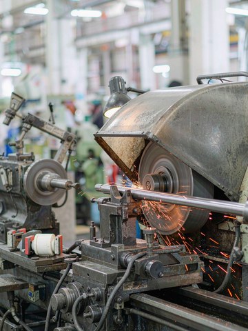
Material choice does half the work here. The shafts that take landing loads are usually 17-4PH stainless in H900 condition, HRC 40 to 48: strong enough for impact, corrosion resistant enough for a robot that leaves the lab. Housings favor aluminum for weight, with steel inserts where wear concentrates. Our stainless steel machining guide covers the 17-4PH family.
3. Why these tolerances are hard to hold
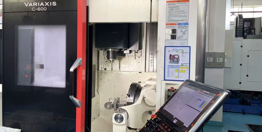
Three reasons, in order of how often they bite. First, hardening distortion: 17-4PH moves when it ages, so the route has to be machine, heat treat, then grind, never machine everything before hardening and hope. Second, stack-up: a housing machined in three setups accumulates origin errors that a single-setup part never sees, which is why we cut intersecting features in one clamping wherever the geometry allows. Third, thin walls on housings grab and relax; torque-controlled clamping and stress relief keep the bores round.
4. How the parts are verified
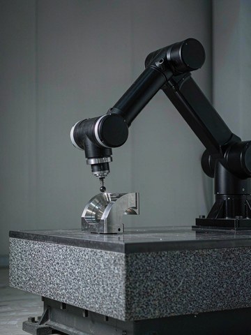
Cross-axis angle, coaxiality, and bearing seat geometry go on Hexagon and Zeiss CMMs. Roughness is checked with a profilometer, chemistry by spectrometer against the mill certificate, and hardness on every heat-treated lot. We publish our standard tolerance at plus or minus 0.005 mm because that is what our process holds in normal production, not a laboratory number. When a robot team sends a drawing, the first-article report covers the axis relationships explicitly, because that is where a silent mistake costs the most. Bearing seats are verified on the CMM, not trusted to the machine's own numbers.
5. What to put on your drawing
Mark the fits and the axis relationships: bearing seat classes, journal coaxiality against a datum, perpendicularity between crossed axes, and the hardness condition if the load case needs it. Leave the rest at standard tolerance and say so. Over-toleranced drawings cost money twice, once in machining and once in inspection, and they slow every quotation. A drawing that says exactly what matters is the cheapest part of a robot program. If you want to see how these numbers play out on a real part, our post on coaxiality on humanoid robot joint parts walks a production case, and the biaxial ankle joint shaft shows the fits on a finished product page.
6. FAQ
Can you match an existing joint shaft?
Yes. Send the drawing with fits and axis relations, or a sample for reverse engineering. Cross-axis angle, journal fits, and hardness are covered in the first-article report.
What is your minimum order for robot joint parts?
No MOQ. We support one-piece prototypes and scale to batch under the same process chain, so the part you test is the part you receive in volume.
How fast can we get a quote?
Send complete 2D and 3D files and you get engineering feedback and a quote within 24 hours.
Which parts do you already produce for robotics?
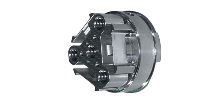
Joint housings, crossed-axis shafts including biaxial ankle joint shafts, reducer covers, and force-torque sensor bodies. See our robotics parts catalog for examples.
If you are tolerancing a joint for a humanoid robot program, send your STEP or IGES models and 2D drawings to kgl@kglmfc.com or request a quote on our RFQ page. We will review the fits, the axis relationships, and the material condition, and return a process assessment and quote within 24 hours.
Related Articles
More from the Robotics & AI series.
Have a project in mind?
Send drawings to kgl@kglmfc.com or request a quote. We respond within 24 hours.
Request a Quote