Robotic Arm CNC Parts: Materials, Tolerances and Lead Times
Robotic arm CNC parts live or die on material choice, interface tolerance and lead time. A working guide to 6061, 7075, 17-4PH and Ti-6Al-4V joints, ±0.005 mm fits and 24 hour quotes.
Key Takeaways
- Robotic arm parts run on three decisions: material per component, the tolerance plan for load carrying interfaces, and a supplier who can reach a verified sample fast.
- ±0.005 mm is KGL's standard commitment across milling, turning and 5-axis work; ±0.002 mm applies to selected 5-axis features with 100 percent CMM verification.
- Most assembly failures start with re-clamping, thin wall ovality or an unstated finish call, not with the machine.
- Quote within 24 hours from complete 2D and 3D files; expedited first articles ship on a scheduled window with no MOQ.
Robotic arm CNC parts are decided by three things before any spindle turns: the material chosen for each component, the tolerance plan for the interfaces that carry load and motion, and a supplier who can move from drawing to a verified sample without weeks of back and forth. Aluminum 6061 and 7075 cover most links and housings. 17-4PH stainless and Ti-6Al-4V take the high-load joint positions. PEEK handles insulation and wear. KGL machines these parts to a ±0.005 mm standard, reaches ±0.002 mm on selected 5-axis features with 100 percent CMM verification, quotes complete 2D and 3D files within 24 hours, and ships expedited first articles on a scheduled window with no MOQ. The rest of this guide puts numbers behind each of those claims, with photographs from our own floor in Shenzhen robotics industry page.
| At a glance | What KGL commits to |
|---|---|
| Materials | 6061-T6, 7075-T651, 6082 and 2219-T851 aluminum; 17-4PH, 304 and 316 stainless; Ti-6Al-4V; PEEK, PEEK1000 and PEI; chromium zirconium copper |
| Standard tolerance | ±0.005 mm across milling, turning and 5-axis work |
| Tight 5-axis features | ±0.002 mm with 100 percent CMM verification, quoted case by case |
| Quote and sampling | Quote within 24 hours on complete 2D and 3D files; expedited first articles on a scheduled window; no MOQ |
| Inspection equipment | Hexagon GLOBALS and ZEISS CAPTUM CMMs, Keyence IM-8010, Mitutoyo gauges, material identity checked by OLYMPUS XRF |
| Documentation | Mill certificates, first article report, CMM results in drawing order, coating records |
| Scale | 100+ CNC machines including 11 five-axis centers, 40+ inspection instruments, 6,000+ m² facility, operating since 2013 |
Which Materials Belong on Which Robotic Arm Components?
Start with inertia. Every gram saved at the wrist multiplies through acceleration, motor sizing and cycle time, which is why most robot builders keep aluminum for links and housings even where steel would survive. The material choice then follows the job the component does. Does it carry load, hold a bearing, sit near a weld tip, or insulate electronics from a conductive frame?
The selection table below is the short version we use in DFM reviews. It reflects what actually ships through our floor rather than a catalog of everything machinable.
| Grade | Where it works | What to know |
|---|---|---|
| 6061-T6 | Long links, covers, brackets, cable guides | Fast to machine, anodizes cleanly, lowest cost per part |
| 7075-T651 | Load carrying links, wrist and joint housings | About twice the yield strength of 6061; watch residual stress on thin walls |
| 6082-T6 | Structural links on European drawings | Frequent callout on EU drawings; sits between 6061 and 7075 |
| 2219-T851 | Welded base structures | In stock for welded frame work |
| 17-4PH stainless | Joint shafts and shock loaded positions | Very high strength and stands up to washdown |
| 304 / 316 stainless | Washdown and food plant arm components | Corrosion resistance first; machining is slower |
| Ti-6Al-4V | Cleanroom, vacuum and surgical arms | Stiff and light; costs more to machine and to inspect |
| PEEK / PEI | Insulators, wear pads, sensor covers | Run without lubrication and isolate electronics from metal dust |
| Chromium zirconium copper | Resistance welding arm tips | Holds conductivity and shape under heat |
Strength and weight decide the structural positions, and the published values below show why 7075-T651 keeps winning wrist housings while 17-4PH keeps winning shafts. Treat them as typical values for the named alloy and temper, since a specific heat lot and section size will move the number a little.
| Grade and condition | Typical yield strength | Density | Where the number earns its place |
|---|---|---|---|
| 6061-T6 | 276 MPa | 2.70 g/cm³ | Baseline for links that only carry bending |
| 6082-T6 | 310 MPa | 2.70 g/cm³ | European drawings often trade 6061 for this grade |
| 7075-T651 | 503 MPa | 2.81 g/cm³ | Roughly 1.8 times the yield of 6061 for wrist and joint housings |
| 2219-T851 | 290 MPa | 2.84 g/cm³ | Weldable, keeps strength near a welded frame joint |
| 17-4PH (H900) | 1170 MPa | 7.80 g/cm³ | Shafts and pins where strength beats weight |
| 304 / 316 | 215 / 205 MPa | 8.00 g/cm³ | Corrosion resistance first, weight is not the driver |
| Ti-6Al-4V | 880 MPa | 4.43 g/cm³ | Around half the weight of steel at comparable strength |
| PEEK | 100 MPa (tensile) | 1.32 g/cm³ | Insulation and wear duty, not structural load |
The trade-offs between the two workhorse aluminum grades are covered in detail in our 7075 vs 6061 comparison and on the aluminum materials hub. For titanium positions, our titanium guide explains why the alloy costs more to machine and how we keep it under control why titanium is hard to machine, titanium machining hub.
What Tolerances Do Robot Arm Interfaces Actually Need?
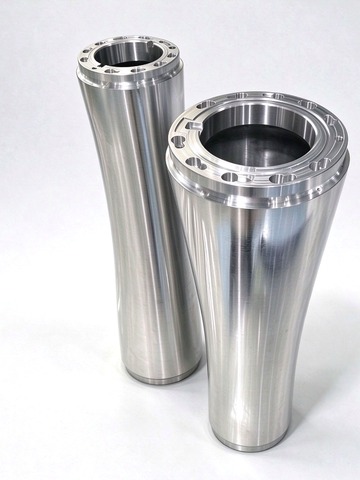
The interfaces decide everything: bearing bores, motor mount seats, flange faces, dowel holes and shaft seats. KGL machines these features to ±0.005 mm as the standard commitment across milling, turning and 5-axis work. On selected 5-axis scenarios we hold ±0.002 mm, and that commitment carries a condition: the features are verified 100 percent on our CMMs, led by a Hexagon GLOBALS with 0.0015 mm measuring capability, and we quote that tolerance only where the geometry allows it. Joint-level callouts deserve their own deep read, and our humanoid robot tolerance article covers them.
Tolerance is not a straight line on a quote. Moving a bore from ±0.05 mm to ±0.005 mm changes tooling, feeds and inspection discipline, and the step from ±0.005 mm to ±0.002 mm costs more than the first move did, because every part then spends time on a temperature-controlled CMM and the process window narrows. That is why we ask which interfaces actually carry the assembly before quoting a blanket tightening.
Flatness and hole position on mounting flanges follow the drawing's GD&T frame rather than a blanket promise. If a drawing tightens every feature beyond what the assembly needs, we push back during DFM and ask which interfaces require the extra precision, because blanket tightening multiplies cost without adding value. Tolerances that stack through a joint are the ones worth the money, and our coaxiality note walks through that stack.
| Interface on robotic arm parts | What we hold | How we verify |
|---|---|---|
| Bearing bores and shaft seats | ±0.005 mm standard | CMM on first article and sampled batches |
| Selected 5-axis critical fits | ±0.002 mm, quoted case by case | 100 percent CMM verification, conditions noted |
| Mounting flange flatness | Per drawing GD&T frame | CMM scan against the drawing datum |
| Dowel and bolt hole position | Per drawing GD&T frame | CMM position check |
How Does the Machining Route Hold Those Numbers?
Fixture strategy comes first. A joint housing with bores on three compound angles needs one setup that reaches them all, so we route it to a Mazak VARIAXIS C-600 five-axis center 5-axis CNC machining. Bore-to-bore position stays honest because the part never re-clamps between operations.
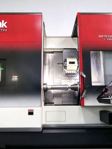
Long arm tubes and cylindrical links go to Mazak INTEGREX i-250H mill-turn centers, where turning and milling happen in one clamping and wall thickness stays concentric. Soft jaws are bored in place for each tube diameter, and thin wall tubes run on expanding mandrels so the clamping force never distorts the finished surface. Smaller brackets and sensor mounts run on our 4-axis cells, and the turn mill machining page shows the tube side of that work.
| Feature pattern | Typical machine | Why it lands there |
|---|---|---|
| Housing with bores on compound angles | Mazak VARIAXIS C-600 5-axis | One setup reaches every face, so no re-clamping error stacks between bores |
| Long tube with turned OD and milled flats | Mazak INTEGREX i-250H mill-turn | Turning and milling in one clamping keeps wall thickness concentric |
| Shafts, pins and threaded seats | CNC turning cells | Roundness and thread quality on a single axis |
| Brackets, sensor mounts, small plates | 4-axis cells (FANUC ROBODRILL) | Short cycles, simple fixtures, low setup cost |
Sampling behaves the same way on every route. Expedited first articles ship on a scheduled window with no MOQ and one-piece sampling supported rapid prototyping. When an order repeats, the same fixtures, offsets and tool lists come back out, and the first piece off each batch gets a full CMM run before the rest of the batch proceeds.
Why Do Robotic Arm Parts Fail at Assembly?
Most robotic arm part problems do not appear at the machine. They appear when the joint is assembled, when the arm is exercised under load, or when the customer's incoming inspection opens a CMM report that disagrees with the drawing. These five patterns come up in our DFM reviews more than any others, and each one traces back to a decision made before cutting.
- Bore to bore misalignment. Finish a housing in three setups and every re-clamp adds a small angular error that stacks across the part. Routing the bores into one 5-axis setup removes the stack instead of tightening it.
- Ovality that shows up after unclamping. A thin wall bore measures round in the fixture and out of round on the table, because the wall was carrying the clamping load. Expanding mandrels and symmetrical stock removal take that load off the wall.
- Flange face drift after stress relief. Plate stock releases internal stress as material comes off, so a face that was flat before anodizing can move afterwards. Roughing both sides evenly and finishing after a stress step holds the face.
- Surface finish that traps what the joint cannot tolerate. Seal faces, vacuum flanges and cleanroom arms fail on roughness rather than dimensions, which is why the drawing needs an Ra callout and not just a note about appearance.
- A report that does not answer the question asked. A CMM report listed out of drawing order forces the buyer to reconstruct the check. We export results in drawing order with the datum scheme stated.
All five are cheaper to fix in a DFM review than in a second production run, and none of them call for exotic equipment. They call for a plan that starts at the interface and treats the fixture as part of the tolerance.
What Does the Inspection and Documentation Package Include?
Verification starts before chips fly. Incoming material arrives with mill certificates, and we check identity on an OLYMPUS XRF analyzer so the grade in the quote is the grade on the table.
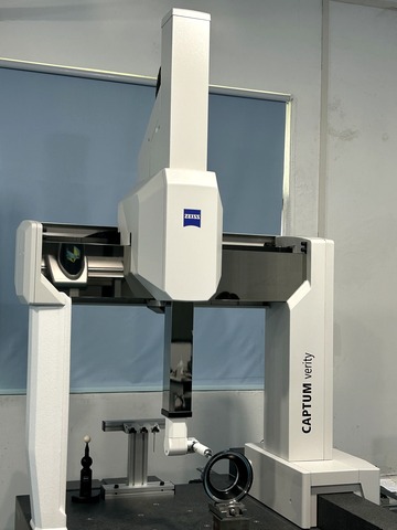
First articles get a full layout against the drawing on Hexagon GLOBALS or ZEISS CAPTUM CMMs, and the report travels with the parts. In process, operators check features with Mitutoyo gauges, and the Keyence IM-8010 handles quick profile and batch checks without waiting for the CMM. On production batches, a defined sampling plan runs alongside the full CMM check on the first piece. The inspection and QC page lists the metrology room equipment, and tolerance standards states what we publish about capability.
A shipment leaves with a document set, not just a box of parts:
- Mill certificates for the exact heat lot that was machined
- First article inspection report against the drawing, with the datum scheme named
- CMM results for critical features, listed in drawing order
- Surface finish and coating records, including the processor used
- A named contact who knows the part number and can answer a metrology question
Buyers assembling arms thousands of kilometers away rarely see our floor, so the paperwork carries the trust: material certificates, CMM reports, and a named contact who answers questions about a measurement instead of resending a PDF.
What Actually Drives the Cost of a Robotic Arm Part?
Ask two suppliers for the same arm housing and the quotes can land 40 percent apart. The gap rarely comes from greed. It lives in five places, and knowing them turns a negotiation into an engineering conversation.
- Material and stock form. A 7075 plate costs more per kilo than 6061, and a near net extrusion or forging can cut cycle time enough to pay for itself. Odd stock sizes add cost again through leftover material.
- Tolerance and inspection depth. Every feature that needs a CMM check spends machine time and metrology time, and 100 percent verification is a real line item, not a free extra.
- Setup count and fixtures. A dedicated fixture amortized across a repeat order is cheap. A one-off fixture built for a single part is not.
- Finish. Anodizing, hard anodizing, passivation, plating and masking each add outside processing plus handling risk between shops.
- Batch size and scheduling. Programming, setup and first article are fixed costs that shrink per part as quantities grow inside one material and fixture family.
The practical response is unglamorous but effective. Group parts that share a material and a fixture family into one order. Ask for CMM verification where the assembly needs it rather than everywhere. Send the mating parts or a photo of the assembly so we can name the features that matter. We mark the cost drivers in the quote so the buyer can see where money goes instead of negotiating one number in the dark.
How Does a Batch of Arm Housings Stay Consistent Across Repeat Orders?
Consistency starts with repeatable setups. We machine robotic arm housings from 7075-T651 on a MAZAK VARIAXIS C-600 5-axis center, locating off ground fixture datums with a 0.003 mm indicator zero-set. Critical bore positions repeat within ±0.010 mm across consecutive batches, verified on our Zeiss CAPTUM CMM. Average cycle time is 45 minutes per housing; carbide tools run on fixed-life schedules (end mills retired at 40 parts) to eliminate wear drift. First-article inspection covers 100% of critical dimensions; every 10th part is then CMM-sampled, sustaining a 99.6% first-pass yield across repeat orders.
What Does a Real Robotic Arm Parts Project Look Like?
One of the world's largest collaborative robot manufacturers trusted us with its joint housing family: wrist housings, shoulder links, and servo adapter plates. Machined from 7075-T651 on MAZAK 5-axis and 9-axis turn-mill centers, critical bearing bores hold ±0.005 mm with 0.01 mm datum runout. The program ships 400 units quarterly on 4-week cycles, DDP to Europe. Every batch clears 100% CMM first-article inspection plus Zeiss verification of critical features; AS9100D and ISO 13485 systems keep documentation audit-ready. Twelve months, zero returns across repeat orders.
What Controls Lead Time and How Do You Shorten It?
Material comes first. Common aluminum plates and bars stay in stock, so machining can start the day the drawing is approved. Special grades, titanium and certain plastics need procurement time, and our quotes state that openly instead of hiding it in the delivery date.
The drawing package comes second. A complete 2D and 3D set lets us quote within 24 hours. Missing tolerances or late revisions restart the clock, so it pays to freeze the interface callouts before sending files.
Inspection depth comes third. Tight features verified on the CMM add time per piece, so ask for that verification only where the assembly needs it. Grouping parts from the same material family into one order trims setup count and handling, and a rolling forecast lets us hold the right stock before the purchase order lands. Prototype and production quantities can even share one order, which is how the path from prototype to production stays short.
What to send for a fast quote:
- A 2D drawing with GD&T, material grade and finish callouts
- A 3D model in STEP or IGES
- A critical feature list if tolerances stack through the assembly
- Quantity and target date, including sample and production splits
How Do You Choose a Robotic Arm Parts Supplier?
Supplier evaluation for robotic arm parts comes down to evidence you can check before a purchase order leaves your desk. These are the questions we would ask another shop, and the answers we publish about ourselves.
- Are the machines real and specific? Photos of actual 5-axis and mill-turn centers cutting arm components tell you more than a capability list with no model numbers.
- Does the tolerance promise carry conditions? A claim of ±0.002 mm means nothing until it states which features, on which machine, verified how.
- Which CMMs stand in the quality room, and do reports ship with the parts? Brand, model and a report that travels with the lot remove arguments later.
- How is material identity confirmed? XRF against the mill certificate closes the loop between the grade quoted and the grade machined.
- Do the certifications match your industry? AS9100D carries weight in aerospace programs, ISO 13485 in medical ones, and ISO 9001:2015 covers the general case.
- Are fixtures dedicated or improvised? Ask how the part will be located on the second run, not just the first.
- Does the quote state material availability? A delivery date that ignores stock reality is the most common source of late parts.
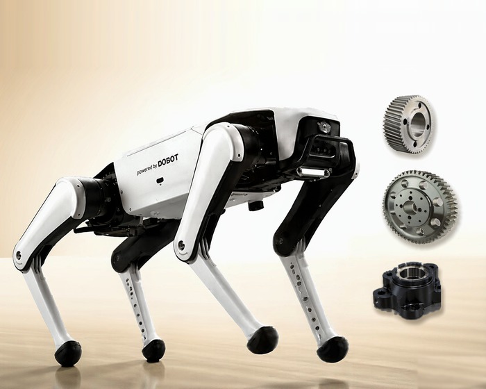
Robotic arm work touches several pages here. The robotics industry page shows the part families we run, turn mill machining covers long tube work, low volume CNC machining covers the bridge between prototype and repeat order, and the quadruped robot parts article is the closest companion read for legged platforms, where the same joint discipline applies.
What Changes Between a Prototype Arm Part and a Production Order?
A first article and the thousandth part are not the same job. Prototype work is judged on speed and on whether the design closes. Production work is judged on repeatability, documentation and cost per part. Both run on the same equipment here, but three things change between them, and knowing which three keeps an RFQ honest.
Prototype parts, including one-piece sampling, ship on a scheduled window with no MOQ rapid prototyping because the price carries programming and setup. A production order spreads those fixed costs across the run, so the per part number drops once the fixture exists and the inspection plan is fixed. The bridge between the two is the prototype to production handover, where the fixture, offsets and inspection plan from the sample become the baseline for every later batch.
| What changes | Prototype run | Production order |
|---|---|---|
| Fixtures | Standard vises and soft jaws machined to the model | Dedicated fixture located off ground datums, stored with the program |
| Inspection | Full layout to confirm every feature on the first article | First article plus a defined sampling plan on the rest of the batch |
| Cost per part | Programming and setup carried by a small quantity | Setup and first article spread across the run, so the unit price falls |
| Documentation | Dimensional report and material certificate | The same package per batch, with lot traceability |
The honest version is that a prototype price is a poor predictor of a production price, and a production price means little without the fixture and inspection plan behind it. Send both quantities in one RFQ when you know them, and the quote can show where the crossover sits instead of hiding it.
Frequently Asked Questions
What tolerance can you hold on robotic arm parts?
±0.005 mm is our standard commitment across milling, turning and 5-axis work. Selected 5-axis features reach ±0.002 mm with 100 percent CMM verification, quoted case by case where the geometry allows.
Which materials do you machine most often for robot arms?
6061-T6 and 7075-T651 aluminum lead the list, followed by 17-4PH stainless, 304 and 316, Ti-6Al-4V and engineering plastics such as PEEK. Chromium zirconium copper covers resistance welding arm tips.
Do you support prototype quantities and small batches?
Yes. No MOQ applies to prototypes, one-piece sampling is supported, and expedited first articles ship on a scheduled window.
How do you verify parts before shipment?
First articles get a full CMM layout on Hexagon GLOBALS or ZEISS CAPTUM machines with the report included. Material identity is checked by XRF against the mill certificate, and production batches follow a defined sampling plan.
Which certifications back your quality system?
KGL is certified to ISO 9001:2015, AS9100D and ISO 13485:2016 and has operated as a custom precision parts manufacturer in Shenzhen since 2013. Our quality page [quality](/quality/) lists the certificate details.
How fast can you quote and sample a robotic arm part?
Send complete 2D and 3D files and the quote comes back within 24 hours, including material availability and inspection notes. Expedited first articles ship on a scheduled window.
Can you machine robotic arm parts in titanium?
Yes. Ti-6Al-4V is a regular job for wrist and cleanroom components, and we quote the extra cycle time and cutter wear openly instead of burying them in the price. Our titanium guide explains where that cost comes from and how it is controlled.
Do you handle anodizing and other finishes?
Anodizing, hard anodizing, passivation, plating and laser marking run through qualified outside processors we have worked with for years. Finish callouts are verified against the drawing before the parts ship.
What is the smallest quantity you will run for a robotic arm part?
One piece. No MOQ applies, and prototype and production quantities can share a single order so the fixture, offsets and inspection plan carry over to the repeat run.
This article is for informational purposes only. Material properties and machining recommendations are based on industry standards and KGL's internal process data. Always validate grade selection, tolerances and finishing requirements against your specific application and relevant regulatory standards before production. (c) 2026 KGL. All rights reserved.
Related Articles
More from the Robotics & AI series.
Have a project in mind?
Send drawings to kgl@kglmfc.com or request a quote. We respond within 24 hours.
Request a Quote