Laser Marking an Anodized Aluminum Part: What Changes and What Does Not
How laser marking behaves on anodized aluminum: contrast on Type II and Type III coatings, why dimensions and tolerance faces stay intact, mark-before versus mark-after anodizing, and the marking sizes that stay readable.
Key Takeaways
- A fiber laser marks anodized aluminum by altering or removing the dye in the oxide pores. Most marks sit inside the coating thickness, so the metal underneath is not cut.
- Contrast is a coating property, not a laser setting. Black dye on Type II gives the brightest mark, clear anodize gives the weakest, and Type III hard anodize usually needs more power or a second pass to reach the same contrast.
- Marking before anodizing buries the mark under the oxide and lowers contrast. Marking after anodizing gives the strongest readability for serial numbers and Data Matrix codes and is our default for traceable data.
- Laser marking does not move a dimension. Anodizing does, because the coating grows both inward and outward, so coating buildup has to be handled in the pre-anodize machining size.
- Keep marks off sealing faces, bearing bores, thread flanks and thin walls, and never let a mark cross a mating surface. On the drawing, specify content, location, character height and code size.
Laser marking is the last operation on many anodized aluminum parts, and it is the one that generates the most avoidable questions. Buyers want to know whether the beam cuts through the coating, whether the serial number will still read after anodizing, and whether a mark on a tight tolerance face ruins the part. The short answer is that a fiber laser marking an anodized surface works on the coating, not on the metal, and that contrast is a function of the anodize type and dye rather than of the laser alone.
KGL machines aluminum parts to ±0.005 mm as standard, with tighter control down to ±0.002 mm on specific five-axis features verified on Hexagon and Zeiss CMMs. Marking runs as part of the same finishing chain as anodizing, so the two steps are planned together instead of in sequence by accident. The shop runs 100+ CNC machines, including 11 five-axis centers, and has built precision parts in Shenzhen since 2013.
1. Does Laser Marking Damage an Anodized Aluminum Part?
Anodizing converts the aluminum surface into an aluminum oxide layer that grows out of the substrate. Type II sulfuric anodize typically lands between 5 and 25 µm, and Type III hard anodize runs thicker, commonly 25 to 50 µm. The layer is porous during the process, which is how dye gets in, and it is sealed afterwards to close the pores.
A fiber laser at 1064 nm heats a small spot of that coating. On a dyed part, the energy bleaches or removes the dye in the pores, which is what produces a light mark on a dark background. Because the coating is thin, a well controlled mark stays inside it. Typical marking depths on anodized aluminum sit in the range of a few micrometres up to roughly 20 µm depending on the setting, and that is the same order as the coating itself. There is no cutting tool, no clamping force beyond the fixture, and no burr to remove afterwards, which is why marking is usually the safest operation to run on a finished surface.
The risk is not the depth. It is the location. A mark placed on a sealing face, an o-ring gland, a bearing bore or a thread flank can break the surface condition that the tolerance was protecting. We treat marking as a surface operation with a keep-out zone, not as a decoration applied wherever there is space.
2. What Changes and What Does Not
Separating the two columns prevents most marking arguments before they reach the shop.
| Item | Effect of laser marking | Effect of anodizing |
|---|---|---|
| Part dimensions | None outside the marked spot; depth stays in the coating | Real. Coating grows roughly half inward and half outward, so a 20 µm coating moves the surface about 10 µm per side |
| Tolerance faces | Unchanged if the mark keeps clear of them | Unchanged if buildup is allowed for before anodizing |
| Coating integrity | Local dye removal; full coating removal only with a deep engraving setting | Full coverage by definition |
| Corrosion resistance | Unaffected while the oxide below the dye stays continuous | Improves; sealing closes the pores |
| Wear surfaces | Mark depth adds no load path | Hard anodize is the wear layer, so never mark across it if the mark would sit in a sliding contact |
| Appearance | Changes locally, by design | Changes globally, including color and gloss |
The practical consequence is that the marking decision belongs with the anodize decision. If the part is going to be hard anodized for wear, marking is planned for a non-functional face and the coating thickness is written on the drawing as a tolerance, not as a note.
3. Why Contrast Depends on the Anodize Type and Color
The laser only changes what is in front of it. That is why two identical parts marked with identical settings can look completely different.
| Anodize finish | Mark appearance | Practical notes |
|---|---|---|
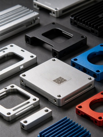
| Type II, black or dark dye | Light silver to white on dark | Highest contrast of the common finishes. The default for serial numbers, Data Matrix codes and readable text |
| Type II, medium dye (blue, red, grey) | Pale mark, moderate contrast | Workable for text. Verify code readability before a run starts, because reader margins get tight |
| Type II, clear or natural | Grey to white on light grey | Lowest contrast. Fine for engraved style logos, weak for machine-read codes |
| Type III hard anodize | Light mark on dark grey or black | Thicker, denser coating. Usually needs more power, a slower speed or a second pass to reach full contrast |
| Anodized and dyed to a light color | Dark grey mark | The beam alters the oxide and, with deeper settings, reaches the metal below. Contrast is directional and must be sampled |
One more variable sits underneath all of this: the aluminum grade. The 6000 series anodizes to a clean, uniform coating, and 7000 series grades are darker and less even after the same process because of their alloying elements. A part in 7075 will not match a part in 6061 for mark brightness, and no laser setting will fix an alloy difference. Our aluminum alloy guide covers that split in more detail.
4. Mark Before or After Anodizing?
This is the decision that most often gets made by accident, usually because two documents disagree about the sequence.
Mark after anodizing is our default for anything traceable. Serial numbers, Data Matrix codes, date codes and any mark that a reader has to decode get applied to the finished coating, because that is the only way to control contrast directly. The trade-off is that a rejected part cannot be re-marked without disturbing the coating, and a re-anodize will change the appearance of an existing mark.
Mark before anodizing puts the mark under the oxide. The coating then protects it, and the mark cannot be abraded off in service, which suits shallow identification marks on parts that see handling and wear. The cost is contrast. The oxide scatters light, so the mark reads flatter and softer, and a deep mark just becomes a visible texture instead of a bright line. Choose this route for a logo or a mold cavity number, not for a code that a scanner has to read.
Whichever route is chosen, it goes on the drawing as a sequence note, not as an assumption. We have seen the same part number marked both ways by two suppliers because the drawing never said which came first.
5. How Does Laser Marking Compare With Dot Peen and Chemical Etching?
| Method | How it acts on anodized aluminum | Typically used for |
|---|---|---|
| Fiber laser marking | Non-contact. Bleaches or removes dye locally; keeps the oxide continuous at normal settings | Variable data, serial numbers, Data Matrix codes, logos on finished parts |
| Deep laser engraving | Removes the coating and cuts a shallow relief into the metal below | Permanent marks on non-tolerance faces, keyed features, visual contrast on clear anodize |
| Dot peen | Impact marking. Punches a pattern of dots, roughly 0.05 to 0.2 mm deep, and can raise material around each dot | Low cost variable data on castings and heavy parts where surface finish does not matter |
| Chemical etching | Stencil and electrolyte. Removes the dyed layer without heat, so no heat affected zone | Curved and cylindrical anodized surfaces, large logo areas, batch mark plates |
Dot peen is the one to avoid on precision work. It deforms metal, it can crack a hard anodized layer, and on a wall under 2 mm it can mark through to the inside surface. It is cheap and permanent, which is why it stays popular on castings, but it has no place on a part with a ±0.005 mm feature nearby.
6. DFM Rules That Keep a Mark Readable
Marking failures are almost always drawing failures. These are the numbers we work to.
| Rule | Working value | Why |
|---|---|---|
| Human readable character height | 1.0 mm minimum on machined surfaces | Below that, anodize oxide texture closes up the strokes |
| Character stroke width | At least 0.15 mm | Thin strokes fill with coating and lose definition |
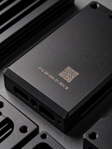
| Data Matrix module size | 0.25 mm minimum, 0.3 to 0.4 mm preferred | Readers need a clean cell edge; smaller modules fail verification after sealing |
| Quiet zone around a code | At least two module widths, clear of edge breaks | A chamfer or radius running through the quiet zone kills readability |
| Distance to a mating or sealing face | 1 to 2 mm minimum | Keeps the mark out of the contact and sealing footprint |
| Marking depth callout | 0.02 mm maximum on finished parts unless specified otherwise | Holds the operation inside the coating on cosmetic and semi-functional faces |
| Location | On a datum-referenced face, drawn on the 2D print | Removes ambiguity about which face is markable |
Two placement habits save rework. Keep the marking area away from radius transitions and parting lines, because the laser focus drifts as the surface curves. And keep marks out of pockets deeper than the lens working range, since defocus widens the line and softens the edge.
7. How Do We Verify a Mark Before It Ships?
Marking evidence is simple to collect and it prevents arguments at the incoming dock. On a first article we record the mark location against the drawing, measure character height, scan each 2D code with a reader and keep the read result with the inspection package. A tape pull on the first piece confirms that the dye removal is clean rather than flaking, and a light abrasion rub confirms the mark survives normal handling.
Where the part also carries dimensional callouts near the marking zone, those features still get measured on the CMM after anodizing and marking, so the report shows that the marking operation changed nothing that mattered. That mirrors the way we handle the rest of a first article, which is described in our first article and CMM workflow. Coating thickness itself is verified by the anodizer against the thickness tolerance on the drawing.
8. What Should Be on the Drawing and in the RFQ?
Four lines of information turn marking from a negotiation into a specification. State the content, meaning the text, the code type and whether the data is fixed or variable per part. State the location, with a small detail view showing which face and which corner. State the size, with character height and module size. State the standard if the program has one, such as a UID or Data Matrix requirement, and note whether the mark goes before or after anodizing.
Send the 2D drawing with the marking block plus the 3D model, name the anodize type and color, and say what the code has to do downstream, meaning whether it will be read by a scanner or by a person. Complete files come back with a quote within 24 hours through our quote process, sampling runs on a scheduled window, and there is no minimum order quantity, so a single marked piece can be run to prove contrast and readability before a batch is released.
The engineering reference pages hold the background numbers: the surface finish reference for the finishes around marking, and the aluminum quick reference for grades and tempers. If the part is already anodized and the question is which coating to choose, start with anodizing types I, II and III, and pair it with surface finish options when the mark sits next to a brushed or as-machined face.
Frequently Asked Questions
Will laser marking remove the anodized coating?
At normal settings it does not. The beam acts on the dye inside the oxide pores and leaves the coating continuous, so corrosion resistance and appearance hold outside the marked area. Deep engraving settings do cut through the coating and into the metal, which is why depth is specified on the drawing when a permanent relief mark is wanted.
Can you laser mark Type III hard anodized parts?
Yes. The thicker, denser coating needs more power, a slower marking speed or a second pass to reach the same contrast as Type II. Contrast is also softer on hard anodize because the surface is more diffuse, so we sample the first part and confirm readability before the run continues.
Does the mark survive anodizing when I mark first?
The mark survives, but the appearance changes. Marking before anodizing puts the mark under the oxide, so it cannot be abraded off in service, while contrast drops because the coating scatters light. That route suits logos, cavity numbers and shallow identification marks. Serial numbers and Data Matrix codes are marked after anodizing.
What is the smallest text or code you can mark?
For human readable text we work from 1.0 mm character height with strokes of at least 0.15 mm. For Data Matrix codes the practical minimum module size is 0.25 mm, with 0.3 to 0.4 mm preferred so a reader still verifies the code after sealing and handling.
Do you mark precision parts in house or through a processor?
Marking and anodizing run through qualified processors inside our standard finishing chain, with the same inspection handoff as machining. First article marking is verified for location, size and code readability, and the read result travels with the inspection package.
Can a mark change a tight tolerance on the marked face?
Not when the mark is properly placed. Marking depth stays in the coating on finished parts, so a mark on a non-functional face has no effect on a ±0.005 mm feature elsewhere. If the mark must land on a functional face, we specify a marking depth limit and measure that face after marking. Note that anodizing itself does move surfaces, because the coating grows outward as well as inward, so buildup is accounted for in the pre-anodize machining size. The tolerance position is documented on our tolerance standards page.
This article is for informational purposes only. Marking contrast, coating thickness and tolerance capability depend on alloy, temper, part geometry and anodize specification. Content reflects general machining and finishing practice at KGL and public engineering references; it is not a substitute for a project specific review. Send your drawing for a binding assessment. (c) 2026 KGL. All rights reserved.
Related Articles
More from the Design for Manufacturing series.
Have a project in mind?
Send drawings to kgl@kglmfc.com or request a quote. We respond within 24 hours.
Request a Quote