Circular Runout vs Total Runout: How Rotating Parts Get Verified
Circular runout reads one cross section, total runout reads the whole surface. Here is what each symbol controls, when a drawing should use which, a worked reading example, and how a shop separates real runout from the runout its own fixture created.
Key Takeaways
- Runout is a composite control: one indicator reading contains the form, orientation and location error of a surface, which is why it matches how rotating parts fail in service but cannot tell you which of the three caused the reading.
- Circular runout is applied at a single cross section, with the part turning 360 degrees about the datum axis and the indicator held still. It says nothing about any other section of the surface.
- Total runout keeps the part turning and adds a traverse along the surface, so its zone is two coaxial cylinders and the whole length must stay between them.
- A part can pass circular runout and fail total runout. A taper, a bow or a misaligned far end only shows up once the indicator travels.
- A runout tolerance is a total, never a plus or minus value, and the number in the frame is the largest swing the surface may produce against the datum axis.
Runout is the tolerance most rotating parts are actually judged by, and it is also the one most often misread on a drawing. It does not measure a size and it does not measure a location. It measures how far a surface moves when the part turns about a datum axis, and it does that with the cheapest inspection setup on the shop floor: a dial indicator and a way to spin the part.
This is the fifth article in our GD&T series, after form, orientation and location tolerances. It covers what circular runout and total runout each control, when a drawing should use which of the two, a worked reading to show how the numbers behave, and how a shop separates real runout from the runout its own fixture created.
1. Why runout exists at all
Every other geometric control isolates one thing. Straightness judges a line against itself. Perpendicularity judges a feature against a datum. Position fixes where an axis may sit. Runout does the opposite: it deliberately bundles three error sources into a single number and asks only one question, which is whether the surface runs true when the part turns.
The reading on the indicator contains the form of the toleranced surface, its orientation relative to the datum axis, and its location relative to that axis. Nothing in the setup separates them. That is a limitation and also the reason runout is used so widely: a bearing, a seal lip or a gear seat does not care which of the three error sources is present, it only cares about the total movement at the contact point. Runout is written in the units the application actually experiences.
The second reason is inspection cost. A bench centre, a V block or a simple arbor plus a dial indicator verifies runout in seconds, on the shop floor, without a CMM program. On high volume turned work that difference decides whether a callout is checked on every part or only on a first article.
2. Circular runout: one cross section at a time
Circular runout is applied to a single cross section. The part rotates one full turn about the datum axis, the indicator stays where it is, and the difference between the highest and the lowest reading is compared against the value in the frame. For a cylindrical surface the zone is two concentric circles in the measuring plane, radially separated by the tolerance value and centred on the datum axis. For a face, the same idea becomes two parallel planes perpendicular to the datum axis, which is why a face runout callout and an OD runout callout use the same symbol but produce different geometry.
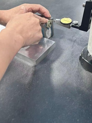
The practical trap is that one cross section says nothing about the rest of the surface. A journal checked only at its inboard end can be perfectly round and perfectly centred there while the outboard end sits on a different axis. Drawings handle this by calling circular runout at two or three defined sections, or by moving to total runout. When a drawing gives a single circular runout value on a long journal with no sections marked, that is worth a question before the part is made, because the answer changes the setup and can change the price.
On the floor, the setup matters more than the indicator. Between centres or on a V block the datum axis is established by the centres, which is why centre holes have to be clean and undamaged. Held in a chuck, the datum axis is whatever the jaws produce on the day, and a part that reads good in one chuck can read out in another. A 0.01 mm dial indicator is adequate for most callouts; a 0.001 mm lever gauge with a small ball tip is used when the value in the frame is tighter than 0.02 mm, and the ball has to ride the real surface rather than a chamfer or a burr.
3. Total runout: the whole surface at once
Total runout keeps the part turning and adds a second motion. The indicator traverses along the surface, parallel to the datum axis, across the full length of the toleranced feature while the part rotates. The zone is no longer a pair of circles in one plane. It is two coaxial cylinders separated by the tolerance value, and every point of the toleranced surface has to fall between them.
Because the indicator travels, the reported value is no longer a single maximum minus minimum at one section. It is the total movement of the whole surface against the datum axis. A taper shows up. A bow shows up. A journal that is perfect at the ends and tight in the middle shows up. This is the callout to use when the entire surface functions, for example a spindle nose where a tool holder seats along its length, a taper seat, or a long bearing journal that has to run true inside a sleeve.
Total runout also controls the relationship of every cross section to the datum axis, since the two zone cylinders are coaxial with it. That makes it stricter than circular runout at the same numeric value, and more expensive to verify: the traverse needs a guided indicator or a CMM with a rotary table and a controlled axial move, not a bench centre and a steady hand.
4. Choosing between the two
The two callouts share a symbol family and are routinely confused, so here is the comparison we use when a customer asks which one belongs on a drawing.
| Point | Circular runout | Total runout |
|---|---|---|
| Zone | Two concentric circles in one plane, or two parallel planes for a face | Two coaxial cylinders covering the full length of the surface |
| Part motion | Rotation only | Rotation plus axial traverse of the indicator |
| Reads | Maximum minus minimum at one cross section | Maximum movement across the entire surface |
| Catches | Roundness, concentricity and orientation error at that section | The same, plus taper, bow and section to section variation |
| Typical equipment | Bench centres or V block with a dial indicator | Guided traverse stand or CMM with rotary table |
| Relative cost of checking | Low, seconds per part on the floor | Higher, needs a guided setup or a programmed cycle |
| Use it when | The function is local: a seal face, a bearing seat at one place, a gear register | The whole surface functions: a taper seat, a spindle nose, a long journal in a sleeve |
The rule we give is to point at the part and name the place that has to run true. If that place is one band, circular runout at that band is enough and it will be cheaper to verify. If the answer is the entire surface, circular runout will pass parts that fail in service, and total runout is the honest callout even though it costs more to check.
5. A worked reading, and where the two callouts diverge
Ahead of the shop case in the next section, a worked example, so every number below can be followed without taking a supplier on trust. Take a turned shaft with a 40 mm journal. The drawing gives circular runout 0.02 mm on the journal, referenced to a datum axis established from the two centre holes, and a separate total runout of 0.03 mm on the same journal to the same datum.
On the bench, the indicator is a 0.001 mm lever gauge and the shaft turns in centres. Readings are taken at four index positions at the inboard section of the journal: 0.000, plus 0.006, minus 0.011 and plus 0.002 mm. The highest reading is plus 0.006 and the lowest is minus 0.011, so the circular runout at that section is 0.017 mm. Against the 0.02 mm callout the part passes, and the report notes that this section used 85 percent of its zone.
Now the same journal is checked to total runout with the indicator traversing along the surface while the shaft turns. The tightest section shows the same 0.017 mm swing. Further along the journal the swing grows, and the largest value seen anywhere on the surface is 0.034 mm. Total runout is that largest value, so the part reads 0.034 mm against a 0.03 mm callout and fails.
Nothing about the first reading was wrong. The inboard section is round and centred, the far end of the journal is not on the same axis, and only the traverse exposes it. This is the single most useful thing to understand about the two callouts: identical hardware, identical datum, and opposite verdicts, because one of them never looked at the rest of the surface.
Two cautions on the arithmetic. First, a runout value is a total permitted swing, so the reading is the highest number minus the lowest, and it is never written as plus or minus. Second, the reading belongs to the surface the tip actually touched. A gauge riding a chamfer, a burr or a paint mark reports the feature it found, not the feature the drawing toleranced.
6. Shop floor case: a flanged motor shaft with every feature on one datum axis
The part below is one we quoted and machined: a flanged motor shaft in aluminum 6061-T6, 133.3 mm long overall, with a 95 mm flange and stepped journals running from 31 mm up to 85 mm. The drawing puts a 0.02 mm circular runout callout on every journal against a common datum axis A-B established from the two centre holes, and 0.03 mm on the flange and step faces against the same axis. Seven diameters and a set of faces, all judged against one axis, which is the quiet way a drawing says the part has to run true as a whole, not pass feature by feature.
The datum choice is also what makes the part honest to inspect on the floor. Because A-B comes from the centre holes, the drawing is describing a between centres check, which is how the assembled motor sees the shaft anyway. On the bench the shaft runs between centres with the centre pressure held between 10 and 15 N·m, a 0.001 mm lever gauge reads one section per journal while the shaft turns through a full revolution, and a V block supports the part for the fastest first-line screen. Anything disputed goes to the CMM: each journal is probed in three sections of sixteen points, a least squares cylinder is fitted to each set, and the reported runout is the largest radial departure of those cylinders from the datum axis.
Two parts came off the line for a full report. Every runout reading fell inside its zone: the radial journal readings landed between 0.001 and 0.014 mm, and the axial face readings between 0.010 and 0.020 mm, so the worst radial reading consumed 70 percent of its 0.02 mm zone. The detail worth carrying into your next shaft drawing is where that margin comes from. The centre holes were machined in the same setup as the journals, so the datum axis the inspection uses is the same axis the cutting tool used. When centre holes and toleranced diameters are produced in separate setups, the runout budget is spent on the setup change before the first chip is cut. The same between centres discipline appears in this shaft machining case, and the turning equipment behind it is listed on the turning equipment page.
7. Fixture eccentricity against real runout
Most runout disputes we see are not about the part at all. They are about the setup, and the customer's incoming check disagrees with our shipping check because the two used different axis references. The common causes are worth listing because they are all detectable before anyone argues.
A chuck that was not bored in place, or soft jaws that were bored at a different clamping pressure, puts the part on an axis the machine does not actually hold. Chips or a burr under a locating face tip the part by an amount that looks exactly like runout. A bent, worn or dirty centre establishes a false datum axis in a between centres setup. A mandrel with its own eccentricity transfers that error straight to the reading. And a part measured warm, straight off the machine, moves as it cools.
The way to separate part error from setup error is to indicate the reference itself before loading the part. On a mandrel, indicate the mandrel. On centres, indicate a master pin between the centres. If the reference already runs out, every number that follows belongs to the fixture. The second test is repetition: measure the same surface at two sections, then re-chuck or index the part by 180 degrees and repeat. Error that follows the part stays with the part. Error that follows the fixture moves when the fixture moves. The third test applies to work held in soft jaws: compare face runout and OD runout on the same part. If both shift together by the same amount, the jaws are the suspect, not the turning.
8. How we verify runout in our shop
Shop floor screening runs on bench centres or a V block with a 0.001 mm lever gauge, which suits turned shafts and flanges and gives a number in seconds. Tight callouts and anything that also needs a reported datum relationship go to the CMM, where the datum axis is built from the centre holes or from the probed datum features in the order stated in the frame, and a rotary table carries the part through a full turn at each section. Reports list the highest and lowest reading, the resulting runout value, and the percentage of the zone consumed, so a part that ships at 85 percent of its allowance is visible as a warning rather than a pass with no comment.
The same discipline carries across our turning and turn mill work and through shaft jobs like this one, where the runout callouts drive the setup rather than following it. The inspection fleet and its verification equipment are listed on the inspection page, and the workflow that decides how many parts get a full report is described in our article on first article inspection.
The wider point from this series holds here as well. A runout report is only as meaningful as the axis it was taken against. Measured against the wrong datum, the number is not strict or lenient. It describes a different part.
Frequently Asked Questions
What is the difference between circular runout and total runout?
Circular runout is measured at a single cross section while the part rotates about its datum axis, and the value is the highest reading minus the lowest at that section. Total runout keeps the part rotating and moves the indicator along the surface, so the value covers the whole length of the toleranced feature and the zone becomes two coaxial cylinders.
Is a runout tolerance a plus or minus value?
Neither. A runout tolerance is a total permitted swing against the datum axis, and the number in the feature control frame is the largest movement the surface may produce. That is why inspectors report a maximum minus a minimum rather than a deviation either side of a nominal.
Can a part pass circular runout and still fail total runout?
Yes, and this is the most common surprise in runout inspection. A journal can be round and centred at the measured section while the rest of the surface is tapered or sitting on a different axis. Only the axial traverse in a total runout check covers the full surface, so it is the callout that catches bow and taper.
How are the two callouts written in a feature control frame?
Both use the same arrow symbol, and the difference is the number of arrows on the leader. A single arrow means circular runout, applied at one cross section. Two arrows mean total runout, applied to the whole surface. The value, the datum references and any modifier follow the same convention as the other geometric characteristics.
How do I tell fixture eccentricity from real runout?
Indicate the reference before loading the part, so a mandrel, arbor or master pin is measured first. Then repeat the check at a second section and again after indexing the part by 180 degrees. Error that stays with the part is real runout, and error that moves with the fixture is setup error. For work in soft jaws, a face and OD reading that shift together by the same amount points at the jaws rather than the turning.
Can KGL inspect and report runout?
Yes. Turned and mill turn work is screened on bench centres with a lever gauge, and tight callouts are reported from the CMM with the datum axis built in the order stated on the drawing. Reports give the maximum and minimum readings, the runout value and the percentage of zone consumed. Send the drawing with the datum scheme and the sections to be checked, and we will confirm the achievable values and the inspection plan at quotation.
This article is general engineering guidance, not a binding manufacturing guarantee. Tolerance feasibility, inspection methods and reporting formats are confirmed per part based on drawings, materials, quantities and process review. Request a formal quotation for part-specific terms. (c) 2026 KGL. All rights reserved.
Related Articles
More from the Inspection & Metrology series.

Have a project in mind?
Send drawings to kgl@kglmfc.com or request a quote. We respond within 24 hours.
Request a Quote