Tight-Tolerance Machining: The Five Steps Behind a 0.005 mm Result
What a shop actually does to hold plus or minus 0.005 mm in production: machine state, workholding, tooling, thermal control, and measurement, written by the technician who runs the finishing passes.
A quote at plus or minus 0.005 mm is a commitment to a process, not to a machine. Any modern CNC can cut one good part at that band; holding it across a batch is a system of five steps that run before, during, and after the cut. This guide describes that system as we run it, written from the finishing passes and the inspection handoff, with the numbers you can check on our floor.
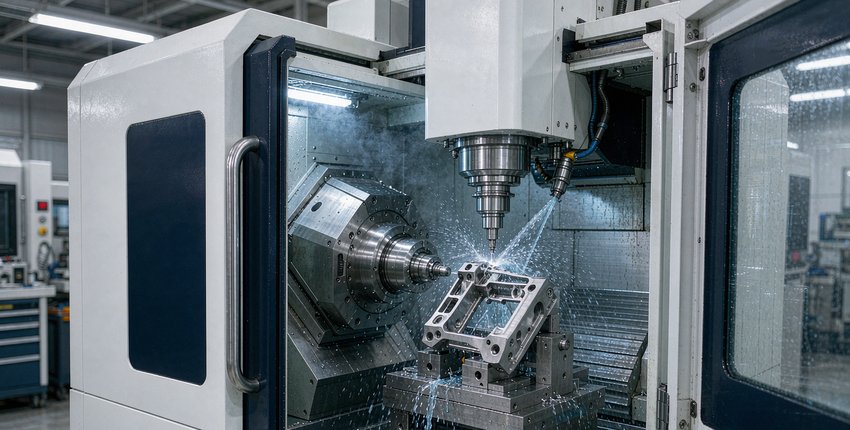
Where 0.005 mm is achievable
Not every feature should carry the band. The table separates what holds reliably from what fights the process, based on production data across the 100+ machines on the floor, including 11 five-axis centers.
| Feature class | Typical achievable band | Main risk to manage |
|---|---|---|
| Bores and diameters, single setup | plus or minus 0.005 mm | Tool wear and thermal drift between cuts |
| Faces and slots, single setup | plus or minus 0.005 mm | Machine warm-up state and clamping load |
| Features across two setups | plus or minus 0.01 to 0.02 mm | Re-indication error between setups |
| Thin walls below 1 mm | plus or minus 0.01 mm and looser | Deflection under the cutter and after release |
| Long features in polymers | plus or minus 0.02 to 0.05 mm | Thermal expansion of the material itself |
Two rules of thumb follow. Keep the tight features on faces machined in one setup, which usually means routing the part to a five-axis center so datums and features share a fixture. And check the material: a stiff 7075 block answers differently from a thin 6061 web, which is why the alloy selection guide belongs in the same folder as the tolerance chart.
Step one: machine state before the first cut
The first step happens before any metal moves. A machine that sat overnight is a different machine from one that has run for an hour: spindles grow, ballscrews warm, and the part moves with them. Our process sheet for tight jobs calls a 30 to 60 minute warm-up cycle that exercises the axes through the range the job will use, then verifies a reference dimension before the first part commits. On the 100+ machines this is scheduled, not remembered.
The scale of the problem is easy to understate. A 300 mm aluminum part growing 0.01 mm over a 1 C change is already two full bands of our quoted tolerance. A cold machine moving toward steady state can drift more than that in the first hour of running, which is why the warm-up is step one and not a suggestion.
Step two: workholding and the datum
The fixture decides whether the tolerance is even measurable. Tight features reference a datum, and the fixture must present that datum to the machine and to the inspector in the same position. Our tight-tolerance jobs run in vises and fixtures that are indicated in on every setup, with the datum face registered against the fixture rather than eyeballed, and the part clocked so the CMM program and the machining program share an origin.
Clamping load is part of step two. A part pulled hard into a vise cuts true and springs when released, so the process uses the lightest clamping that holds against the cut, and critical faces are sometimes finish-machined after a final re-torque. This is where the setup count analysis and the tolerance question meet: every extra setup re-introduces the indication error that step two exists to remove.
Step three: tooling and the finishing pass
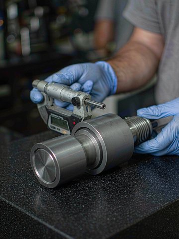
Finishing strategy decides whether the last pass lands in the band. Tight features get a dedicated finishing pass with a sharp, known-geometry cutter, run after the roughing passes have relieved the stock and the part has been allowed to settle. On our floor the finish allowance typically runs 0.15 to 0.3 mm per side, and the finishing pass is cut with the same tool orientation and coolant state as the first article, so the process reproduces itself.
Tool wear is tracked as a schedule, not a surprise. Each cutter has a predicted life in the process sheet, offsets update at defined intervals, and the dimensions that drift with wear are measured between batches rather than after them. A bore that creeps 0.002 mm per hundred parts is caught by the offset schedule long before it exits the band.
Step four: temperature, from the machine to the inspector
The 0.005 mm band is smaller than the thermal motion around it, so temperature control is not a nicety. The machining area is held near 20 C with coolant temperature controlled, and tight jobs are scheduled so the part is not sitting in sun, drafts, or next to a loading door. The inspection side follows the same rule: a 200 mm aluminum part measured at 25 C instead of 20 C reads about 0.02 mm large, which is larger than the tolerance it is being checked against.
Our inspection room runs the same climate, and parts coming from the machine soak before measurement: 2 to 4 hours for aluminum, shorter for steel and titanium, per the process sheet. The tolerance chart reference gives the full control list, because the soak schedule and the CMM uncertainty are part of the quoted tolerance rather than overhead.
Step five: measurement with a calibrated reference
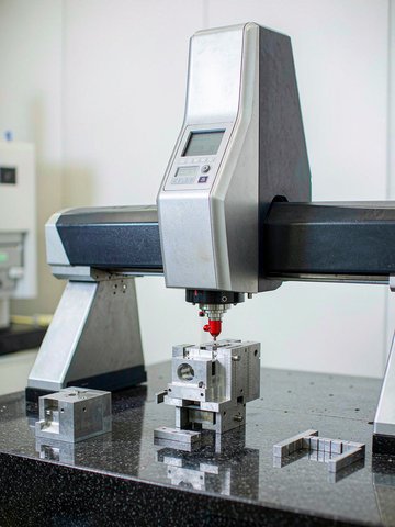
The last step proves the first four. Every tight feature is measured against a calibrated reference: micrometers and bore gauges for the fast checks, and a bridge CMM for the layout, with rated uncertainty around 0.0015 mm, a third of the band it verifies. The measurement plan defines how many points, where, and at what temperature, and the CMM program reproduces the datum frame from step two.
The inspection report that leaves with the parts lists actual values for the critical dimensions, not a pass or fail stamp. That is the difference between a claim and evidence, and it is why the 40+ precision inspection devices in our QC room, CMMs, height gauges, surface testers, and form testers, are scheduled on tight jobs like the machines are.
A 30 mm bore, step by step
An example makes the system concrete: a 30 mm bore in 6061-T6, called out at plus 0.005 mm over zero, in a housing with a bearing fit. Roughing leaves 0.5 mm per side. The part soaks while the machine warms through its cycle. A finish pass with a fresh boring bar leaves 0.15 mm. The part is released, soaked again, and measured on the CMM at 20 C. The offset schedule logs the result, and the next part runs the identical sequence. The measured spread across the batch lands inside 0.004 mm, with the CMM report as the record.
Stories from the same system on harder geometry appear in the production blog, for example holding position and profile on an impeller tolerance path and on an optical lens barrel. When the drawing's tight features sit across faces, the five-axis page shows the single-setup route that keeps steps one through five honest. Send the drawing through the quote form and the review will tell you which features carry the 0.005 mm band and which should not.
Frequently asked questions
Can every feature on my part hold plus or minus 0.005 mm?
In one setup, on a rigid feature, yes. Across setups, on thin walls, or on long polymer features, the band is not the right callout. The quote tells you which features hold the band and which get a realistic number, with the reason.
Why does temperature matter for a metal part?
Aluminum grows about 0.02 mm per 100 mm per 10 C. A part measured at the wrong temperature reads outside a band it actually meets, so machining and measurement both run near 20 C and parts soak before the reading counts.
What measurement report comes with tight-tolerance parts?
A first-article CMM layout and a final inspection report with actual values for the critical dimensions, plus material certificates with the batch. The report scope is agreed at quotation so the price carries the right inspection.
Does specifying 0.005 mm everywhere make the part better?
No. It makes the process slower and the inspection longer, and tight bands on non-functional features add cost without adding function. Put the band where the fit, the bearing, or the seal needs it and leave the rest to a general tolerance.
More Reference Guides
Charts and decision guides from the KGL engineering desk.
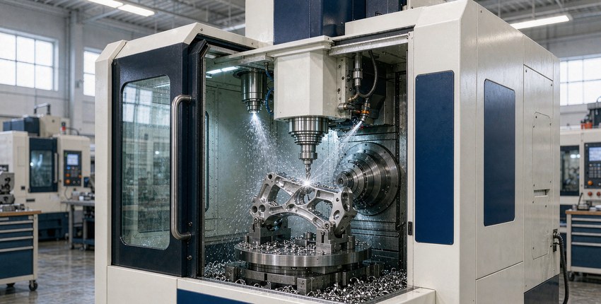
CNC Machining Tolerance Chart: IT Grades and What It Takes to Hold 0.005 mm
Read the reference →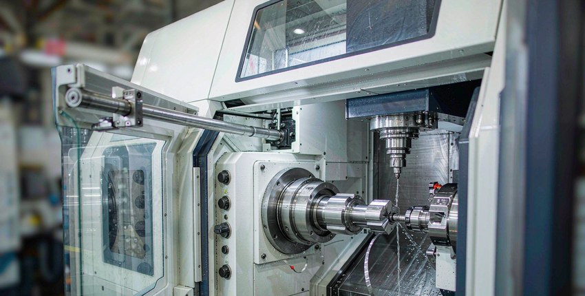
Surface Roughness Ra Chart: What Ra 0.4 to Ra 3.2 Means and What Each Finish Costs
Read the reference →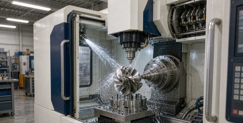
5-Axis vs 3-Axis CNC Machining: Cost, Setups, and When the Upgrade Pays
Read the reference →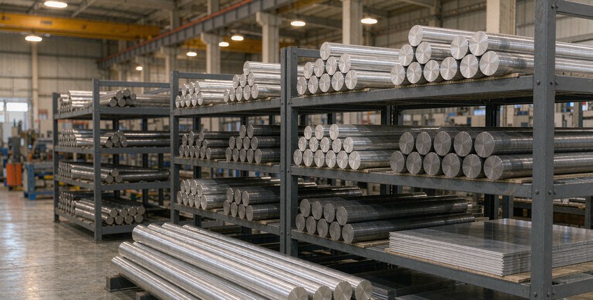
6061 vs 7075 vs Titanium: An Alloy Selection Guide for Machined Parts
Read the reference →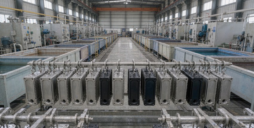
Anodizing vs Chem Film vs Electroless Nickel: Choosing a Finish for Machined Parts
Read the reference →
Stainless Steel 304 vs 316 vs 17-4PH: A Machining Perspective
Read the reference →
CNC Machining Cost Factors: What Actually Drives the Price
Read the reference →
CNC DFM Checklist: 15 Rules to Check Before You Send a Drawing
Read the reference →
GD&T Basics for Machined Parts: Datums, Position, and What Actually Gets Measured
Read the reference →Have a drawing to check?
Send it to kgl@kglmfc.com or request a quote. Engineering review responds within 24 hours.
Request a Quote